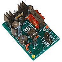
IRPLLED1 International Rectifier, IRPLLED1 Datasheet - Page 15

IRPLLED1
Manufacturer Part Number
IRPLLED1
Description
BOARD EVALUATION FOR IRS2540PBF
Manufacturer
International Rectifier
Specifications of IRPLLED1
Current - Output / Channel
1.5A
Outputs And Type
1, Non-Isolated
Voltage - Output
24V
Features
Dimmable
Voltage - Input
50 ~ 170V
Utilized Ic / Part
IRS2540PBF
Core Chip
IRS2540, IRS2541, IRS25401
Topology
Buck (Step Down)
No. Of Outputs
1
Output Current
1.5A
Output Voltage
500mV
Dimming Control Type
PWM
Development Tool Type
Hardware - Eval/Demo Board
Lead Free Status / RoHS Status
Contains lead / RoHS compliant by exemption
Fig. 20 Low side FET and low side diode comparison, Vin = 100V, Iout = 1.5A, Vout = 17V
Switching losses increase with higher bus voltage. Conduction losses in the lower switch also increase as the
difference between input and output voltages increases, since it conducts for a greater part of the switching cycle. A
MOSFET has much lower conduction losses than a diode since it has a fixed on resistance and not a fixed junction
voltage drop and therefore offers an advantage at higher voltages and currents. A combination of diode and
MOSFET together is also a possibility if required. The IRPLLED1 board allows for an additional MOSFET switch
M2 to be added. In this case, during the dead time, instead of the body diode free-wheeling the additional diode
would be conducting. This will always be the case as long as the forward drop of the external diode is less than that
of the body diode.
If the load current is the low hundred milliamps range, the losses in the diode may not be a concern. For optimized
system efficiency the forward conduction losses of a diode can also be compared to the reverse recovery losses with
a low side MOSFET. For this evaluation board, it was found that conduction losses were less than reverse recovery
losses when running at 1.5A and therefore and diode alone was used..
Selecting the correct MOSFET involves finding a part with as low an RDSon low as possible. MOSFET RDSon
increases for higher VDS rated parts. Therefore, if a 600V MOSFET is used in a 200V application, extra losses may
be incurred due to a component that far exceeds the requirements. If using two MOSFETs the next parameter to be
considered is the reverse recovery time. Obviously MOSFETs will not have a reverse recovery time comparable to
diodes but a reverse recovery time in the order of 150 to 200ns is possible. The two remaining parameters to
consider are direct trade-offs of each other, on resistance and gate charge. If the MOSFET has a relatively low gate
capacitance the die size will be small, which will result in a larger on resistance that could potentially be a problem
for high current applications. On the other hand, if the MOSFET has a larger gate capacitance the die will be
relatively large and the part will have a lower on resistance. In this case more current is needed to turn on the
MOSFET therefore requiring more VCC current in the IRS2540/1/01/11 and resulting in higher losses. There has to
be a direct compromise between the two. Typically the best solution is a MOSFET with a relatively low RDSon and
a medium sized gate capacitance much like the device chosen for this application.
6. VCC Supply
Since the IRS2450/1/01/11 is rated for 200V/600V VBUS can vary considerably in different applications. If a
simple supply resistor from VBUS is used for VCC it will experience high power losses at higher bus voltages. For
higher voltage applications therefore an alternate V CC supply scheme utilizing a resistor feed-back (RS2) from the
output needs to be implemented, as seen in Fig. 1 and Fig. 16. This solution is limited to applications where the LED
string voltage exceeds the voltage required to drive VCC, which is about 13V to guarantee good operation.
RD-0608
15
www.irf.com


