STEVAL-ILL027V1 STMicroelectronics, STEVAL-ILL027V1 Datasheet - Page 8
STEVAL-ILL027V1
Manufacturer Part Number
STEVAL-ILL027V1
Description
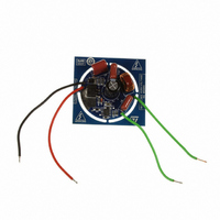
BOARD EVAL LED DRIVER FOR L6562A
Manufacturer
STMicroelectronics
Datasheets
1.L6562ADTR.pdf
(26 pages)
2.STEVAL-ILL027V1.pdf
(4 pages)
3.STEVAL-ILL027V1.pdf
(23 pages)
Specifications of STEVAL-ILL027V1
Design Resources
STEVAL-ILL027V1 Schematics STEVAL-ILL027V1 BOM STEVAL-ILL027V1 Gerber Files
Current - Output / Channel
260mA
Outputs And Type
1, Non-Isolated
Voltage - Output
70V
Features
Short-Circuit Protection
Voltage - Input
120VAC
Utilized Ic / Part
L6562A
Product
Display Modules
Lead Free Status / RoHS Status
Lead free by exemption / RoHS compliant by exemption
Other names
497-10170


Circuit design
8/23
The frequency is:
Equation 5
The switching frequency varies during the line cycle, which is good for EMI.
The max. frequency occurs at peak input voltage:
Equation 6
The input power is:
Equation 7
Equation 8
The integration term of
only. There is no simple solution form for the integration term. The average value of the input
voltage and duty cycle can be used to perform the estimation. After Ipk is calculated, the
inductance can be determined according to the desired switching frequency range.
The average input voltage over half-cycle at 120 VAC line is:
Equation 9
The average duty cycle is:
Equation 10
Therefore:
Equation 11
After the current is determined, it is necessary to choose the right inductance value. The
inductance affects the running frequency. The maximum switching frequency below 200 kHz
has been chosen.
Equation 8
fsw
Doc ID 16815 Rev 2
fsw
P
(
P
θ
Vave
=
Ipk
)
max
=
Dave
is a constant value, so the power is determined by Ipk
=
2
1
∫
0
T
1
π
=
*
1
2
=
Ipk
=
=
2
1
=
*
∫
L
0
L
L
*
π
*
Vave
Vpk
*
Vave
*
*
1
∫
1
Ipk
Ipk
Ipk
0
π
( D
Pin
Vout
*
(
2
θ
(
+
sin(
Vpk
*
Vout
Vin
* )
Vout
*
Vout
Dave
fsw
Vin
θ
(
θ
+
d )
*
(
)
*
(
Vout
θ
+
θ
Vpk
θ
=
Vin
)
=
dt
d )
Vout
=
0.333
1.2 A
θ
108 V
(
θ
)
)
)
AN3111
Related parts for STEVAL-ILL027V1
Image
Part Number
Description
Manufacturer
Datasheet
Request
R

Part Number:
Description:
BOARD EVAL FOR MEMS SENSORS
Manufacturer:
STMicroelectronics
Datasheet:

Part Number:
Description:
KIT DEV STARTER ST10F276Z5
Manufacturer:
STMicroelectronics
Datasheet:

Part Number:
Description:
BOARD EVAL HDMI $ VIDEO SWITCH
Manufacturer:
STMicroelectronics
Datasheet:

Part Number:
Description:
BOARD DEMO ACCELEROMETER DIL24
Manufacturer:
STMicroelectronics
Datasheet:

Part Number:
Description:
BOARD STLM75/STDS75/ST72F651
Manufacturer:
STMicroelectronics
Datasheet:

Part Number:
Description:
EVAL BOARD 3AXIS MEMS ACCELLRMTR
Manufacturer:
STMicroelectronics
Datasheet:

Part Number:
Description:
BOARD EVAL 8BIT MICRO + TDE1708
Manufacturer:
STMicroelectronics
Datasheet:

Part Number:
Description:
EVAL BOARD A/D TS4657
Manufacturer:
STMicroelectronics
Datasheet:

Part Number:
Description:
BOARD ADAPTER 20DIP LIS3LV02DL
Manufacturer:
STMicroelectronics
Datasheet:

Part Number:
Description:
BOARD DEMO STM8S207R6/LIS331DLH
Manufacturer:
STMicroelectronics
Datasheet:

Part Number:
Description:
STMicroelectronics [RIPPLE-CARRY BINARY COUNTER/DIVIDERS]
Manufacturer:
STMicroelectronics
Datasheet:
Part Number:
Description:
STMicroelectronics [LIQUID-CRYSTAL DISPLAY DRIVERS]
Manufacturer:
STMicroelectronics
Datasheet:
Part Number:
Description:
BOARD EVAL FOR MEMS SENSORS
Manufacturer:
STMicroelectronics
Datasheet: