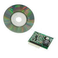
EVL6562A-LED STMicroelectronics, EVL6562A-LED Datasheet - Page 9

EVL6562A-LED
Manufacturer Part Number
EVL6562A-LED
Description
EVALUATION MODULE L6562A
Manufacturer
STMicroelectronics
Type
Power Factor Correctionr
Specifications of EVL6562A-LED
Current - Output / Channel
350mA
Outputs And Type
1, Non-Isolated
Features
Dimmable
Voltage - Input
48V
Utilized Ic / Part
L6562A
Input Voltage
48 V
Product
Power Management Modules
Lead Free Status / RoHS Status
Lead free / RoHS Compliant
Voltage - Output
-
Lead Free Status / Rohs Status
Lead free / RoHS Compliant
For Use With/related Products
L6562A
Other names
497-10420
Available stocks
Company
Part Number
Manufacturer
Quantity
Price
AN2983
2.3
The falling edge of the gate driver starts the toff delay (see
end of the toff delay the set input of the FF is activated and a new cycle begins.
Figure 7.
FOT (fixed off time) delay circuit
Figure 8.
The fixed off time delay circuit is implemented by connecting the gate drive (GD) output to
the ZCD input by means of a diode D5 in series with R11 and C7 (in parallel), and ZCD to
ground with R18 and C8 in parallel.
There is a clamp circuit behind the ZCD pin of the controller that limits the maximum voltage
to 5.7 V, and a comparator whose output goes high if the input voltage falls below the
threshold level of 0.7 V.
Hence when GD is high (10 V nominal), ZCD is forced to the clamp level of 5.7 V, but as
soon as the gate driver goes low, the diode D5 turns off and the capacitor C8 discharges
through R18 until the voltage reaches 0.7 V.
At this point the comparator switches on and triggers the set input of the flip-flop, whose
output goes high.
Simulated waveforms
FOT net
Doc ID 15679 Rev 1
Section 2.3 on page 9
Circuit description
). At the
9/32


