EVL6562A-LED STMicroelectronics, EVL6562A-LED Datasheet
EVL6562A-LED
Specifications of EVL6562A-LED
Available stocks


Related parts for EVL6562A-LED


EVL6562A-LED Summary of contents
Page 1
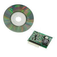
... Since, from a system point of view, the second solution seems more viable, we have developed an application to investigate the possibility of employing an L6562A to implement such a constant current controller. This document describes the EVL6562A-LED demonstration board and summarizes the relevant results obtained. Figure 1. EVL6562A-LED: L6562A constant current inverse buck driver module ...
Page 2
Contents Contents 1 Main characteristics . . . . . . . . . . . . . . . . . . . . . . . . . . . . . . . . . . . ...
Page 3
... Figure 25. Short-circuit detection . . . . . . . . . . . . . . . . . . . . . . . . . . . . . . . . . . . . . . . . . . . . . . . . . . . . . 23 Figure 26. Load current decay . . . . . . . . . . . . . . . . . . . . . . . . . . . . . . . . . . . . . . . . . . . . . . . . . . . . . . . 23 Figure 27. LED current (average, maximum, minimum Figure 28. LED current (ripple Figure 29. Switching frequency . . . . . . . . . . . . . . . . . . . . . . . . . . . . . . . . . . . . . . . . . . . . . . . . . . . . . . 25 Figure 30. Efficiency [%] . . . . . . . . . . . . . . . . . . . . . . . . . . . . . . . . . . . . . . . . . . . . . . . . . . . . . . . . . . . 25 Figure 31. LED current (average Figure 32. Switching frequency . . . . . . . . . . . . . . . . . . . . . . . . . . . . . . . . . . . . . . . . . . . . . . . . . . . . . . 26 Figure 33. Efficiency [%] . . . . . . . . . . . . . . . . . . . . . . . . . . . . . . . . . . . . . . . . . . . . . . . . . . . . . . . . . . . 26 Figure 34. EVL6562A-LED electrical schematic . . . . . . . . . . . . . . . . . . . . . . . . . . . . . . . . . . . . . . . . . 27 Doc ID 15679 Rev 1 List of figures 3/32 ...
Page 4
... CC current drivers through a dedicated bus. ● the LEDs strings. The CC drivers are the modules considered in this application note and implemented in the EVL6562A-LED demonstration board. Figure 2. System configuration 1.2 Requirements The board’s design takes into account the following key points. ...
Page 5
... AN2983 1.3 Interface Ideally the module should have only two pins and behave as a constant current sink, but for practical reasons, and in order to gain a higher degree of flexibility, its connector has the following pinout. Table 1. EVL6562A-LED interface Pin number ● D_Dimm is a digital (TTL) input for the module. A high level shuts off the circuit. A low ...
Page 6
... Circuit description 2 Circuit description The following is a list of the main components that form the module EVL6562A-LED. ● Power section ● L6562A controller ● Fixed off time (FOT) delay ● Current setting ● LED number compensation ● Shutdown/dimming ● Auxiliary power ● ...
Page 7
AN2983 Figure 4. Standard buck converter Other than the power and ground connections being exchanged, there are no differences between the two configurations; the behavior and dimensioning of the inverse buck are the same as that of the standard buck. ...
Page 8
Circuit description Equation 5 Equation 6 2.2 L6562A controller The L6562A is used in a "fixed off time" and "peak current mode" topology. represents the controller with its main functional blocks, the FOT_Delay circuitry and the power section. Figure 6. ...
Page 9
AN2983 The falling edge of the gate driver starts the toff delay (see end of the toff delay the set input of the FF is activated and a new cycle begins. Figure 7. Simulated waveforms 2.3 FOT (fixed off time) ...
Page 10
Circuit description This causes the gate driver to go high again and then the power MOSFET to conduct. The time delay toff is simply governed by the equation of the discharge of the capacitor C8 through the resistor R18 with ...
Page 11
AN2983 If we consider the time at which the capacitor voltage crosses the 0.7 V threshold, the equivalent toff time is 1.32 µS (+150 nS compared to the nominal value, due to the tolerance of C8 and stray capacitance) while ...
Page 12
Circuit description Equation 11 Equation 12 Neglecting the current that flows though the CS pin (1 µA max): Equation 13 And then: Equation 14 Equation 15 Then: Equation 16 and: Equation 17 Equation 18 Equation 19 Equation 20 Equation 21 ...
Page 13
AN2983 Equation Led _ pk (max Led Doc ID 15679 Rev 1 Circuit description + ⎛ ⎞ ⎜ ⎟ nom * ) ⎝ ⎠ Ra 13/32 ...
Page 14
Circuit description Where, as already seen, the (nominal) LED peak current is: Equation 23 On the other hand fix I_Led_pk = 0 we can estimate the value of Va for which the LED current is reduced to zero. ...
Page 15
AN2983 Figure 12. I_Led/V_trim 2.5 LED number compensation The average output current depends on the number of LEDs connected to the module more precise, on the voltage (VLed) developed across them. This is due to the fact ...
Page 16
Circuit description The drawback of this configuration is that since the circuit is now more sensitive to input voltage variations, Vin has to be more tightly regulated. The following equations demonstrate what has been previously asserted. Equation 33 Equation 34 ...
Page 17
AN2983 Going into further detail, we also have to consider the delay of the current sense comparator (tdel) and modify Equation 40 With: Equation 41 Equation Led + VLed Equation Led + VLed And ...
Page 18
Circuit description And then: Equation 49 On the demonstration board several measures have been taken with Vin = 48 V, and kΩ. Figure 13 is the plot of the LED current as a function of the voltage ...
Page 19
AN2983 Ω 100 pF, and D1= 5.6 V Zener diode. All these devices have been Note: introduced to protect the controller from excessive input voltages or noise complete system, with a ...
Page 20
Circuit description Figure 16. Dimming 1% CH(4) green: LED current [mA] CH(1) red: gate drive output [V] CH(3) purple: D_Dimm input [V] Figure 18. Dimming 50% CH(4) green: LED current [mA] CH(1) red: gate drive output [V] CH(3) purple: D_Dimm ...
Page 21
AN2983 Figure 19. Dimming 90% CH(4) green: LED current [mA] CH(1) red: gate drive output [V] CH(3) purple: D_Dimm input [V] 2.7 Auxiliary power The components for the auxiliary power supply are Q1, D2, C2, R2, R3, and R5. This ...
Page 22
Circuit description 2.8 Open-/short-circuit protection As indicated, one of the requirements is that the module can sustain open and short circuits indefinitely and restart the correct functionality as soon as the fault is removed. From the "open circuit" point of ...
Page 23
AN2983 resistor, Q3 turns off allowing C5 to charge through R6, and the voltage of the INV pin rises again. When it reaches 0.45 V the disable condition is removed and the controller restarts. If the short-circuit condition is removed, ...
Page 24
Measurements 3 Measurements 3.1 LED voltage dependency The first set of measures was taken at a nominal input voltage with Vin = 48 V and with the output voltage (Vled parameter. Figure 27. LED current (average, maximum, minimum) ...
Page 25
AN2983 Figure 29. Switching frequency Figure 30. Efficiency [%] Doc ID 15679 Rev 1 Measurements 25/32 ...
Page 26
Measurements 3.2 Input voltage dependency A second set of measures was taken varying the input voltage from with several load conditions as parameters (VLed from V). Figure 31. LED current (average) Figure 32. ...
Page 27
... AN2983 4 Electrical schematic and bill of materials Figure 34. EVL6562A-LED electrical schematic Electrical schematic and bill of materials Doc ID 15679 Rev 1 27/32 ...
Page 28
... Electrical schematic and bill of materials Table 2. EVL6562A-LED BOM Item Qty Reference C2,C3, C6,C8, C10 D4,D5,D6,D7, D8, EXT EXT LEDs 13 1 EXT R1,R12,R19 R4,R5,R13 R10 28 1 R11 29 1 R14 30 2 R15,R16 31 1 R17 32 1 R18 33 1 R20 28/32 Part PCB footprint 0.22 µF 100VL ...
Page 29
... AN2983 Table 2. EVL6562A-LED BOM (continued) Item Qty Reference 34 1 R21 Electrical schematic and bill of materials Part PCB footprint 470 805 L6562A SO-8 Doc ID 15679 Rev 1 Notes STMicroelectronics 29/32 ...
Page 30
... References 5 References 1. AN2928 2. AN2782 3. L6562A datasheet Note: These references are available on the STMicroelectronics web site at www.st.com. 30/32 Doc ID 15679 Rev 1 AN2983 ...
Page 31
AN2983 6 Revision history Table 3. Document revision history Date 16-Dec-2009 Revision 1 Initial release. Doc ID 15679 Rev 1 Revision history Changes 31/32 ...
Page 32
... Information in this document is provided solely in connection with ST products. STMicroelectronics NV and its subsidiaries (“ST”) reserve the right to make changes, corrections, modifications or improvements, to this document, and the products and services described herein at any time, without notice. All ST products are sold pursuant to ST’s terms and conditions of sale. ...