NCP5602EVB ON Semiconductor, NCP5602EVB Datasheet - Page 8
NCP5602EVB
Manufacturer Part Number
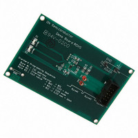
NCP5602EVB
Description
EVAL BOARD FOR NCP5602
Manufacturer
ON Semiconductor
Specifications of NCP5602EVB
Design Resources
NCP5602 EVB BOM NCP5602EVB Gerber Files NCP5602 EVB Schematic
Current - Output / Channel
60mA
Outputs And Type
2, Non-Isolated
Voltage - Output
4.8 ~ 5.7 V
Features
Dimmable
Voltage - Input
3.6V
Utilized Ic / Part
NCP5602
Core Chip
NCP5602
Topology
Charge Pump
No. Of Outputs
2
Development Tool Type
Hardware - Eval/Demo Board
Leaded Process Compatible
Yes
Mcu Supported Families
NCP5602
Rohs Compliant
Yes
Lead Free Status / RoHS Status
Lead free / RoHS Compliant
For Use With/related Products
NCP5602
Other names
NCP5602EVBOS


X being the Read/Write identifier as defined by the I2C
specification. Since the NCP5602 does not return data, the
first byte of the I2C frame shall be 1001 1110 ($9E) as
depicted in Table 2.
Dimming
accurately control the output current flowing in the two
LED. Such dimming is active under the NORMAL mode
only and the LED2 current cannot be adjusted when the
ICON mode is active.
[B7,B6] = RFU:bits reserved for future use
B5
ICON
Table 1. NCP5602 Physical I2C Address
Table 2. LED−REG[0..7] Internal Register Bits Assignment
The physical address of the NCP5602 is 1001 111X, the
The built−in I2C interface provides a simple way to
B7
1
RFU
B7
= ICON:control the NORMAL/ICON
= Low ³ Normal MODE takes place, the two
B6
0
mode of operation:
LED are activated and the current can be
adjusted from 0 mA to 30 mA maximum
per LED.
B5
0
RFU
B6
B4
1
B3
1
Figure 9. Typical NCP5602 I2C Startup Sequence
ICON
B5
B2
1
B1
1
IREF*16*16
http://onsemi.com
B4
B0
0
8
be sent by the MCU. The frame contains three consecutive
bytes and shall fulfill the I2C specifications:
First byte
Second byte : internal register address
Third byte
(0 mA to 30 mA, Assuming Rext = 10 kW)
output current update.
content of the SDA byte sent by the external MCU as
depicted in Table 2. For typical application, the 60 mA
reference current forced by the external resistor is
multiply by 16 to get a 1.0 mA/step in the output
LED. The waveforms given Figure 10 illustrate a normal
programming sequence.
ICON
[B4..B0]= Output LED current. The content of these bits
are disconnected when LED−REG=$00.
IREF*16*8
To set up a new output current value, a full frame shall
The waveforms given in Figure 9 illustrate a typical
The internal register LED−REG[0..7] is set up by the
The DC−DC converter is switched OFF and the two LED
B3
= High ³ ICON mode takes place, LED#1 is
deactivated, the current to LED#2 being setup
to 450 mA. It is not possible to adjust this
current.
is latched to the current reference on the 8
clock pulse.
: I2C address
: output current value
IREF*16*4
B2
IREF*16*2
B1
³$9E
³$01
³$00 to $1E
IREF*16
B0
th
SCK
Related parts for NCP5602EVB
Image
Part Number
Description
Manufacturer
Datasheet
Request
R

Part Number:
Description:
High Efficiency Ultra Small Thinnest White LED Driver
Manufacturer:
ON Semiconductor
Datasheet:
Part Number:
Description:
ON Semiconductor [VOLTAGE REGULATOR]
Manufacturer:
ON Semiconductor
Datasheet:
Part Number:
Description:
357-036-542-201 CARDEDGE 36POS DL .156 BLK LOPRO
Manufacturer:
ON Semiconductor
Datasheet:
Part Number:
Description:
357-036-542-201 CARDEDGE 36POS DL .156 BLK LOPRO
Manufacturer:
ON Semiconductor
Datasheet:
Part Number:
Description:
357-036-542-201 CARDEDGE 36POS DL .156 BLK LOPRO
Manufacturer:
ON Semiconductor
Datasheet:
Part Number:
Description:
357-036-542-201 CARDEDGE 36POS DL .156 BLK LOPRO
Manufacturer:
ON Semiconductor
Datasheet:
Part Number:
Description:
357-036-542-201 CARDEDGE 36POS DL .156 BLK LOPRO
Manufacturer:
ON Semiconductor
Datasheet:
Part Number:
Description:
357-036-542-201 CARDEDGE 36POS DL .156 BLK LOPRO
Manufacturer:
ON Semiconductor
Datasheet:
Part Number:
Description:
357-036-542-201 CARDEDGE 36POS DL .156 BLK LOPRO
Manufacturer:
ON Semiconductor
Datasheet:
Part Number:
Description:
357-036-542-201 CARDEDGE 36POS DL .156 BLK LOPRO
Manufacturer:
ON Semiconductor
Datasheet:
Part Number:
Description:
357-036-542-201 CARDEDGE 36POS DL .156 BLK LOPRO
Manufacturer:
ON Semiconductor
Datasheet:
Part Number:
Description:
357-036-542-201 CARDEDGE 36POS DL .156 BLK LOPRO
Manufacturer:
ON Semiconductor
Datasheet:
Part Number:
Description:
Manufacturer:
ON Semiconductor
Datasheet:
Part Number:
Description:
Manufacturer:
ON Semiconductor
Datasheet: