LM3423MHBKBSTEV/NOPB National Semiconductor, LM3423MHBKBSTEV/NOPB Datasheet - Page 27
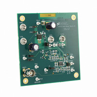
LM3423MHBKBSTEV/NOPB
Manufacturer Part Number
LM3423MHBKBSTEV/NOPB
Description
BOARD EVAL BUCK BOOST LM3423
Manufacturer
National Semiconductor
Series
PowerWise®r
Specifications of LM3423MHBKBSTEV/NOPB
Current - Output / Channel
1A
Outputs And Type
1, Non-Isolated
Voltage - Output
35V
Features
Dimmable
Voltage - Input
4.5 ~ 35V
Utilized Ic / Part
LM3423
Lead Free Status / RoHS Status
Lead free / RoHS Compliant
Other names
LM3423MHBKBSTEV


The current rating should be at least 10% higher than the
maximum average diode current (I
Buck
Boost and Buck-boost
Replace D
average diode current (I
(V
11. OUTPUT OVLO
For boost and buck-boost regulators, output OVLO is pro-
grammed with the turn-off threshold voltage (V
the desired hysteresis (V
To set V
Boost
Buck-boost
A small filter capacitor (C
the OVP pin to ground to reduce coupled switching noise.
12. INPUT UVLO
For all topologies, input UVLO is programmed with the turn-
on threshold voltage (V
(V
Method #1: If no PWM dimming is required, a two resistor
network can be used. To set V
FD
HYS
), solve for the nominal power dissipation (P
).
TURN-OFF
MAX
with D in the I
, solve for R
D
TURN-ON
). Given a diode with forward voltage
HYSO
OVP
OV1
= 47 pF) should be added from
D-MAX
). To set V
HYS
) and the desired hysteresis
:
, solve for R
D-MAX
equation to solve for the
):
HYSO
, solve for R
UV2
TURN-OFF
D
:
):
) and
OV2
:
27
To set V
Method #2: If PWM dimming is required, a three resistor net-
work is suggested. To set V
and solve for R
R
13. PWM DIMMING METHOD
PWM dimming can be performed several ways:
Method #1: Connect the dimming MosFET (Q
to the nDIM pin and the source to AGND. Apply an external
PWM signal to the gate of Q
necessary to properly turn off Q
Method #2: Connect the anode of a Schottky diode to the
nDIM pin. Apply an external inverted PWM signal to the cath-
ode of the same diode.
The DDRV pin should be connected to the gate of the dimFET
with or without level-shifting circuitry as described in the PWM
Dimming section. The dimFET should be rated to handle the
average LED current and the nominal output voltage.
14. ANALOG DIMMING METHOD
Analog dimming can be performed several ways:
Method #1: Place a potentiometer in series with the R
resistor to dim the LED current from the nominal I
zero.
Method #2: Connect a controlled current source as detailed
in the Analog Dimming section to the CSH pin. Increasing the
current sourced into the CSH node will decrease the LEDs
from the nominal I
the thermal foldback circuit.
UVH
:
TURN-ON
UV1
, solve for R
LED
as in Method #1. To set V
to zero current in the same manner as
UV1
DIM
TURN-ON
:
. A pull down resistor may be
3
.
, assume R
3
) with the drain
HYS
UV2
www.national.com
LED
, solve for
= 10 kΩ
to near
CSH
Related parts for LM3423MHBKBSTEV/NOPB
Image
Part Number
Description
Manufacturer
Datasheet
Request
R

Part Number:
Description:
National Semiconductor [8-Bit D/A Converter]
Manufacturer:
National Semiconductor
Datasheet:
Part Number:
Description:
National Semiconductor [Media Coprocessor]
Manufacturer:
National Semiconductor
Datasheet:
Part Number:
Description:
Digitally Controlled Tone and Volume Circuit with Stereo Audio Power Amplifier, Microphone Preamp Stage and National 3D Sound
Manufacturer:
National Semiconductor
Datasheet:
Part Number:
Description:
Digitally Controlled Tone and Volume Circuit with Stereo Audio Power Amplifier, Microphone Preamp Stage and National 3D Sound
Manufacturer:
National Semiconductor
Datasheet:
Part Number:
Description:
AC97 Rev 2 Codec with Sample Rate Conversion and National 3D Sound
Manufacturer:
National Semiconductor
Part Number:
Description:
Manufacturer:
National Semiconductor
Datasheet:
Part Number:
Description:
Manufacturer:
National Semiconductor
Datasheet:
Part Number:
Description:
General Purpose, Low Voltage, Low Power, Rail-to-Rail Output Operational Amplifiers
Manufacturer:
National Semiconductor
Datasheet:
Part Number:
Description:
8-bit 20 MSPS flash A/D converter.
Manufacturer:
National Semiconductor
Datasheet:
Part Number:
Description:
Low Noise Quad Operational Amplifier
Manufacturer:
National Semiconductor
Datasheet:
Part Number:
Description:
Quad Differential Line Receivers
Manufacturer:
National Semiconductor
Datasheet:
Part Number:
Description:
Quad High Speed Trapezoidal? Bus Transceiver
Manufacturer:
National Semiconductor
Datasheet:
Part Number:
Description:
Dual Line Receiver
Manufacturer:
National Semiconductor
Datasheet:
Part Number:
Description:
TTL to 10k ECL Level Translator with Latch
Manufacturer:
National Semiconductor
Datasheet: