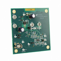
LM3423MHBKBSTEV/NOPB National Semiconductor, LM3423MHBKBSTEV/NOPB Datasheet - Page 13

LM3423MHBKBSTEV/NOPB
Manufacturer Part Number
LM3423MHBKBSTEV/NOPB
Description
BOARD EVAL BUCK BOOST LM3423
Manufacturer
National Semiconductor
Series
PowerWise®r
Specifications of LM3423MHBKBSTEV/NOPB
Current - Output / Channel
1A
Outputs And Type
1, Non-Isolated
Voltage - Output
35V
Features
Dimmable
Voltage - Input
4.5 ~ 35V
Utilized Ic / Part
LM3423
Lead Free Status / RoHS Status
Lead free / RoHS Compliant
Other names
LM3423MHBKBSTEV
CURRENT SENSE/CURRENT LIMIT
The LM3421/23 achieves peak current mode control using a
comparator that monitors the main MosFET (Q1) transistor
current, comparing it with the COMP pin voltage as shown in
Figure
protection function. Current limit is accomplished by a redun-
dant internal current sense comparator. If the voltage at the
current sense comparator input (IS) exceeds 245 mV (typi-
cal), the on cycle is immediately terminated. The IS input pin
has an internal N-channel MosFET which pulls it down at the
conclusion of every cycle. The discharge device remains on
an additional 210 ns (typical) after the beginning of a new cy-
cle to blank the leading edge spike on the current sense
signal. The leading edge blanking (LEB) determines the min-
imum achievable on-time (t
There are two possible methods to sense the transistor cur-
rent. The R
the current sense resistance because the IS pin was designed
to withstand the high voltages present on the drain when the
MosFET is in the off state. Alternatively, a sense resistor lo-
cated in the source of the MosFET may be used for current
sensing, however a low inductance (ESL) type is suggested.
The cycle-by-cycle current limit (I
either method as the limiting resistance (R
FIGURE 6. Current Sense / Current Limit Circuitry
6. Further, it incorporates a cycle-by-cycle over-current
DS-ON
of the main power MosFET can be used as
ON-MIN
LIM
).
) can be calculated using
LIM
):
300673a2
13
OVER-CURRENT PROTECTION
The LM3421/23 devices have a secondary method of over-
current protection. Switching action is disabled whenever the
current in the LEDs is more than 30% above the regulation
set point. The dimming MosFET switch driver (DDRV) is not
disabled however as this would immediately remove the fault
condition and cause oscillatory behavior.
ZERO CURRENT SHUTDOWN
The LM3421/23 devices implement "zero current" shutdown
via the EN and RPD pins. When pulled low, the EN pin places
the devices into near-zero current state, where only the leak-
age currents will be observed at the pins (typical 0.1 µA). The
applications circuits, frequently have resistor dividers to set
UVLO, OVLO, or other similar functions. The RPD pin is an
open drain N-channel MosFET that is enabled only when the
device is enabled. Tying the bottom of all resistor dividers to
the RPD pin as shown in
shutdown, thus removing their current paths and providing
true application-wide zero current shutdown.
FIGURE 7. Zero Current Shutdown Circuit
Figure 7
allows them to float during
www.national.com
300673j1


