LM3423MHBKBSTEV/NOPB National Semiconductor, LM3423MHBKBSTEV/NOPB Datasheet - Page 6
LM3423MHBKBSTEV/NOPB
Manufacturer Part Number
LM3423MHBKBSTEV/NOPB
Description
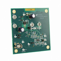
BOARD EVAL BUCK BOOST LM3423
Manufacturer
National Semiconductor
Series
PowerWise®r
Specifications of LM3423MHBKBSTEV/NOPB
Current - Output / Channel
1A
Outputs And Type
1, Non-Isolated
Voltage - Output
35V
Features
Dimmable
Voltage - Input
4.5 ~ 35V
Utilized Ic / Part
LM3423
Lead Free Status / RoHS Status
Lead free / RoHS Compliant
Other names
LM3423MHBKBSTEV


www.national.com
The trade-off will be less accuracy and performance flexibility
for reduced component count, and increased efficiency. The
current limit (I
equation:
The LM3423 evaluation board can be configured for either
high-side PWM dimming or low-side PWM dimming. The def-
inition of high side dimming is when a MOSFET that interrupts
the forward current through the LED stack is placed on the
anode side of the LED stack. Low side dimming places the
MOSFET on the cathode side of the LED stack. The PWM
dimming signal should be applied to either the BNC connector
or test point TP6.
Dimming on the low-side (cathode) of the LED load is enabled
using the jumper configuration described in Table 6.
SHUTDOWN OPERATION
The LM3423 can be configured for either a very low quiescent
current shut down (“Zero Current” IQ < 1 µA), or the standard
enable/disable configuration (I
FIGURE 4. MOSFET R
TABLE 5. MOSFET R
TABLE 6. Low-Side PWM Dimming Configuration
J4A, J4B
Jumper
Jumper
CL
R6
J2
J3
J5
) using this sense method is calculated by the
DS(ON)
DS(ON)
Q
Illustration of Current through LED Stack with PWM Dimming
< 3 mA).
Sensing Configuration
Sensing Configuration
Close Jumper
Close Jumper
Open Jumper
Open Jumper
Operation
Operation
No Load
30080809
6
Substituting in the resistor values as listed in the board
schematic and an R
gives a current limit I
PWM DIMMING
The average LED forward current is often controlled or re-
duced with a pulse-width modulated (PWM) signal. By reduc-
ing the average LED current, light from the LEDs is reduced.
This dimming method allows the converter to operate the
LEDs at a specific peak output current level (i
ally a set point determined by the LED manufacturer. This
allows the LED to illuminate with a consistent light color while
still having the ability to reduce its lumens output.
The dimming frequency should be fast enough so that the ON
and OFF blinking of the LEDs is not perceived by the human
eye. Usually the dimming frequency should be greater than
120 Hz, but less than 5 kHz for best results.
The LM3423 evaluation board implements PWM dimming by
placing a series connected MOSFET in series with the LED
stack. The PWM signal is applied to this MOSFET, and the
LED current is interrupted when the MOSFET turns OFF.
“Zero Current” is achieved by tying the bottom resistor of all
external resistor dividers (i.e. V
18. Bias currents in the resistor dividers are essentially elim-
inated during shutdown. The evaluation board is designed
using the “zero” shutdown feature.
FAULT PROTECTION FLAG
The LM3423 can be configured with fault protection by using
the fault flag indicator FLT (pin 9).
When a fault condition is detected, the FLT pin will go high
(pulled up to V
IN
by resistor R2).
DS(ON)
CL
of approximately 10A.
of 0.025Ω for Q5 (SUD40N10-25)
IN
UVLO, OVP) to the RPD Pin
30080811
L
), which is usu-
Related parts for LM3423MHBKBSTEV/NOPB
Image
Part Number
Description
Manufacturer
Datasheet
Request
R

Part Number:
Description:
National Semiconductor [8-Bit D/A Converter]
Manufacturer:
National Semiconductor
Datasheet:
Part Number:
Description:
National Semiconductor [Media Coprocessor]
Manufacturer:
National Semiconductor
Datasheet:
Part Number:
Description:
Digitally Controlled Tone and Volume Circuit with Stereo Audio Power Amplifier, Microphone Preamp Stage and National 3D Sound
Manufacturer:
National Semiconductor
Datasheet:
Part Number:
Description:
Digitally Controlled Tone and Volume Circuit with Stereo Audio Power Amplifier, Microphone Preamp Stage and National 3D Sound
Manufacturer:
National Semiconductor
Datasheet:
Part Number:
Description:
AC97 Rev 2 Codec with Sample Rate Conversion and National 3D Sound
Manufacturer:
National Semiconductor
Part Number:
Description:
Manufacturer:
National Semiconductor
Datasheet:
Part Number:
Description:
Manufacturer:
National Semiconductor
Datasheet:
Part Number:
Description:
General Purpose, Low Voltage, Low Power, Rail-to-Rail Output Operational Amplifiers
Manufacturer:
National Semiconductor
Datasheet:
Part Number:
Description:
8-bit 20 MSPS flash A/D converter.
Manufacturer:
National Semiconductor
Datasheet:
Part Number:
Description:
Low Noise Quad Operational Amplifier
Manufacturer:
National Semiconductor
Datasheet:
Part Number:
Description:
Quad Differential Line Receivers
Manufacturer:
National Semiconductor
Datasheet:
Part Number:
Description:
Quad High Speed Trapezoidal? Bus Transceiver
Manufacturer:
National Semiconductor
Datasheet:
Part Number:
Description:
Dual Line Receiver
Manufacturer:
National Semiconductor
Datasheet:
Part Number:
Description:
TTL to 10k ECL Level Translator with Latch
Manufacturer:
National Semiconductor
Datasheet: