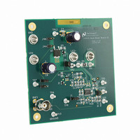
LM3423MHBKBSTEV/NOPB National Semiconductor, LM3423MHBKBSTEV/NOPB Datasheet - Page 5

LM3423MHBKBSTEV/NOPB
Manufacturer Part Number
LM3423MHBKBSTEV/NOPB
Description
BOARD EVAL BUCK BOOST LM3423
Manufacturer
National Semiconductor
Series
PowerWise®r
Specifications of LM3423MHBKBSTEV/NOPB
Current - Output / Channel
1A
Outputs And Type
1, Non-Isolated
Voltage - Output
35V
Features
Dimmable
Voltage - Input
4.5 ~ 35V
Utilized Ic / Part
LM3423
Lead Free Status / RoHS Status
Lead free / RoHS Compliant
Other names
LM3423MHBKBSTEV
The worst case ripple is seen when the input voltage is at its
lowest magnitude. This is true if we can say that the output
voltage stays relatively constant.
Design Example:
V
V
V
V
I
Buck Boost Convertion Ratio:
Therefore:
D @ V
D @ V
t
t
Calculate average input current: The average input current is
equal to the average inductor current.
Assume efficiency = 85%
I
I
Set inductor current ripple for 30% of average current.
ΔI
ΔI
Therefore:
Inductor value @ V
LED
ON
ON
IN
IN
O
IN-MIN
IN-NOM
IN-MAX
IN
IN
= 915 mA @ V
= 1830 mA @ V
≊
= @ V
= @ V
= 1A
= 915 mA x 0.30 = 275 mA
= 1830 mA x 0.30 = 550 mA
28V
IN-MAX
IN-MIN
= 18V
= 36V
= 24V
IN-MAX
IN-MIN
= 0.609
= 0.436
= 1.05 µs
= 0.742 µs
IN
IN
IN-MIN
= 36V
= 18V
≊
33 µH
5
PEAK CURRENT LIMIT
Due to its peak current-mode control architecture, the
LM3423 has inherent cycle-to-cycle current limit control. In-
ductor current flowing through the low-side power MOSFET
(Q5) is sensed as a voltage between IS (pin 17) and PGND
(pin 14). This voltage is fed into an internal comparator which
establishes the peak current allowed during each switching
cycle.
Two methods of switch current sensing are available on the
evaluation board. The first is accomplished through the use
of an external sense resistor which allows for higher accuracy
in sensing the peak current. For the LM3423 evaluation
board, the sense resistor R6 can be utilized using the jumper
configuration as described in Table 4.
The current limit (I
Substituting in the resistor value as listed in the board
schematic gives a current limit I
MOSFET switch current can also be sensed directly across
the R
resistor (see Table 5).
TABLE 4. External R
DS(ON)
FIGURE 3. External R
J4A, J4B
Jumper
of MOSFET Q5, eliminating the need for a sense
R6
J2
J3
CL
) is calculated by the equation:
SENSE
SENSE
CL
Resistor Configuration
of approximately 4.1A.
I
SW
Close Jumper
Open Jumper
Open Jumper
Current Sense
Operation
Populate
30080807
www.national.com


