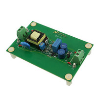
LM3445-120VFLBK/NOPB National Semiconductor, LM3445-120VFLBK/NOPB Datasheet - Page 4

LM3445-120VFLBK/NOPB
Manufacturer Part Number
LM3445-120VFLBK/NOPB
Description
PROGRAMMERS, DEVELOPMENT SYSTEMS
Manufacturer
National Semiconductor
Series
PowerWise®r
Specifications of LM3445-120VFLBK/NOPB
Current - Output / Channel
365mA
Outputs And Type
1, Isolated
Voltage - Output
20V
Features
Dimmable, TRIAC Dimmable
Voltage - Input
90 ~ 135VAC
Utilized Ic / Part
LM3445
Lead Free Status / RoHS Status
Lead free / RoHS Compliant
www.national.com
CURRENT SENSE COMPARATOR
GATE DRIVE OUTPUT
THERMAL SHUTDOWN
THERMAL SHUTDOWN
Note 1: Absolute maximum ratings are limits beyond which damage to the device may occur. Operating Ratings are conditions for which the device is intended
to be functional, but device parameter specifications may not be guaranteed. For guaranteed specifications and test conditions, see the Electrical Characteristics.
All voltages are with respect to the potential at the GND pin, unless otherwise specified.
Note 2: Internal thermal shutdown circuitry protects the device from permanent damage. Thermal shutdown engages at T
= 145°C (typ).
Note 3: Human Body Model, applicable std. JESD22-A114-C.
Note 4: Junction-to-ambient thermal resistance is highly application and board-layout dependent. In applications where high maximum power dissipation exists,
special care must be paid to thermal dissipation issues in board design. In applications where high power dissipation and/or poor package thermal resistance is
present, the maximum ambient temperature may have to be derated. Maximum ambient temperature (T
temperature (T
part/package in the application (R
Symbol
R
V
V
V
R
V
I
FLTR2
T
FLTR2
DRVH
DRVL
t
DRV
DV
θJA
OS
SD
J-MAX-OP
= 125°C), the maximum power dissipation of the device in the application (P
Parameter
FLTR2 open circuit voltage
FLTR2 impedance
Current sense comparator offset voltage
GATE high saturation
GATE low saturation
Peak souce current
Peak sink current
Rise time
Fall time
Thermal shutdown temperature
Thermal shutdown hysteresis
MSOP-10 junction to ambient
θJA
), as given by the following equation: T
A-MAX
4
= T
J-MAX-OP
Conditions
I
I
GATE = V
GATE = V
C
C
(Note
GATE
GATE
load
load
– (R
= 1 nF
= 1 nF
= 50 mA
= 100 mA
4)
θJA
D-MAX
× P
CC
CC
A-MAX
D-MAX
/2
/2
), and the junction-to ambient thermal resistance of the
) is dependent on the maximum operating junction
).
J
= 165°C (typ.) and disengages at T
Min
-4.0
720
-0.77
0.24
0.22
0.88
Typ
750
420
165
121
0.1
15
15
20
Max
0.50
0.50
780
4.0
Units
°C/W
mV
mV
kΩ
ns
°C
V
A
J


