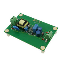
LM3445-120VFLBK/NOPB National Semiconductor, LM3445-120VFLBK/NOPB Datasheet - Page 18

LM3445-120VFLBK/NOPB
Manufacturer Part Number
LM3445-120VFLBK/NOPB
Description
PROGRAMMERS, DEVELOPMENT SYSTEMS
Manufacturer
National Semiconductor
Series
PowerWise®r
Specifications of LM3445-120VFLBK/NOPB
Current - Output / Channel
365mA
Outputs And Type
1, Isolated
Voltage - Output
20V
Features
Dimmable, TRIAC Dimmable
Voltage - Input
90 ~ 135VAC
Utilized Ic / Part
LM3445
Lead Free Status / RoHS Status
Lead free / RoHS Compliant
www.national.com
The off-time of the LM3445 can be programmed for switching
frequencies ranging from 30 kHz to over 1 MHz. A trade-off
between efficiency and solution size must be considered
when designing the LM3445 application.
The maximum switching frequency attainable is limited only
by the minimum on-time requirement (200 ns).
Worst case scenario for minimum on time is when V
its maximum voltage (AC high line) and the LED string voltage
(V
The maximum voltage seen by the Buck Converter is:
INDUCTOR SELECTION
The controlled off-time architecture of the LM3445 regulates
the average current through the inductor (L2), and therefore
the LED string current. The input voltage to the buck converter
(V
each half-cycle of the input line voltage. The voltage across
the LED string is relatively constant, and therefore the current
through R4 is constant. This current sets the off-time of the
converter and therefore the output volt-second product
(V
product makes it possible to keep the ripple through the in-
ductor constant as the voltage at V
The equation for an ideal inductor is:
FIGURE 17. LM3445 External Components of the Buck
LED
BUCK
LED
) is at its minimum value.
x off-time) remains constant. A constant volt-second
) changes with line variations and over the course of
Converter
BUCK
30060340
varies.
BUCK
is at
18
Given a fixed inductor value, L, this equation states that the
change in the inductor current over time is proportional to the
voltage applied across the inductor.
During the on-time, the voltage applied across the inductor is,
Since the voltage across the MOSFET switch (Q2) is rela-
tively small, as is the voltage across sense resistor R3, we
can simplify this to approximately,
During the off-time, the voltage seen by the inductor is ap-
proximately:
The value of V
the LED stack voltage will remain constant. If we rewrite the
equation for an inductor inserting what we know about the
circuit during the off-time, we get:
Re-arranging this gives:
From this we can see that the ripple current (Δi) is proportional
to off-time (t
by V
These equations can be rearranged to calculate the desired
value for inductor L2.
Where:
Finally:
Refer to “Design Example” section of the datasheet to better
understand the design process.
LED
V
L(ON-TIME)
divided by a constant (L2).
OFF
L(OFF-TIME)
) multiplied by a voltage which is dominated
V
= V
L(ON-TIME)
V
BUCK
L(OFF-TIME)
will be relatively constant, because
- (V
= V
LED
BUCK
= V
+ V
LED
- V
DS(Q2)
LED
+ I
L2
x R3)


