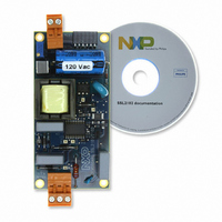
SSL2102T/DB/FLYB120V,598 NXP Semiconductors, SSL2102T/DB/FLYB120V,598 Datasheet - Page 4

SSL2102T/DB/FLYB120V,598
Manufacturer Part Number
SSL2102T/DB/FLYB120V,598
Description
KIT SSL2102 DESIGNER 120V
Manufacturer
NXP Semiconductors
Specifications of SSL2102T/DB/FLYB120V,598
Current - Output / Channel
400mA ~ 1.05A
Outputs And Type
1, Isolated
Voltage - Output
9 ~ 23 V
Features
Dimmable
Voltage - Input
85 ~ 276VAC
Utilized Ic / Part
SSL2102
Duty Cycle (max)
75 %
Mounting Style
SMD/SMT
Switching Frequency
100 KHz
Operating Supply Voltage
8.5 V to 40 V
Supply Current
1.7 A
Maximum Operating Temperature
+ 100 C
Minimum Operating Temperature
- 40 C
Output Power
1.6 W
Package / Case
SOIC-20
Lead Free Status / RoHS Status
Lead free / RoHS Compliant
Lead Free Status / RoHS Status
Lead free / RoHS Compliant, Lead free / RoHS Compliant
Other names
568-4931
NXP Semiconductors
3. Connecting the board
UM10386
User manual
Fig 2.
Board connection diagram
K1;
pin 1: L
pin 2: Earth
pin 3: N
N
1
L
Remark: All components referred to in the text can be located on
schematic diagram”
diagram”.
The board can be optimized for a 230 V 50 Hz or a 120 V 60 Hz mains supply. In addition
to the mains voltage optimization, the board is designed to work with multiple high power
LEDs with a total working voltage of between 9 V and 23 V. The output current can be
limited using trimmer R20. A dedicated LED load that is to be connected to K3 can be
delivered on request. Connector K2 can be used to attach other LED loads. The output
voltage is limited to 25 V. When attaching a LED load to an operational board (hot
plugging) an inrush peak current will occur due to the discharge of capacitor C6. After
frequent discharges, the LEDs may deteriorate or become damaged.
If a galvanically isolated transformer is used, it should be placed between the AC source
and the dimmer/demo board. Connect a user defined LED (string) to connector K2 as
shown in
of this connector.
Remark: When the board is placed in a metal enclosure, the middle pin of connector K1
should be connected to the metal casing for grounding.
K1
9 mm
Figure
All information provided in this document is subject to legal disclaimers.
2. Note that the anode of the LED (string) is connected to the bottom side
and connectors can be found on
Rev. 1 — 1 February 2011
9 mm
9 mm
K2
K3
SSL2102 19 W to 22 W mains dimmable LED driver
−
+
1
6
−
+
1
K2;
pin 1: LED+
pin 2: LED−
K3;
pin 1: LED+
pin 2: LED+
pin 3: LED+
pin 4: LED−
pin 5: LED−
pin 6: LED−
6
1
J1
Figure 2 “Board connection
Figure 8 “Board
UM10386
019aaa806
© NXP B.V. 2011. All rights reserved.
J2
6
1
4 of 24


