MCP4728EV Microchip Technology, MCP4728EV Datasheet - Page 23
MCP4728EV
Manufacturer Part Number
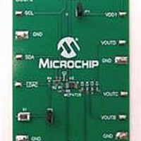
MCP4728EV
Description
BOARD EVAL 12BIT 4CH DAC MCP4728
Manufacturer
Microchip Technology
Type
D/Ar
Specifications of MCP4728EV
Number Of Dac's
4
Number Of Bits
12
Outputs And Type
1, Single Ended
Data Interface
I²C
Settling Time
6µs
Dac Type
Voltage
Voltage Supply Source
Single
Operating Temperature
-40°C ~ 125°C
Utilized Ic / Part
MCP4728
Product
Data Conversion Development Tools
Resolution
12 bit
Interface Type
I2C
Supply Voltage (max)
5.5 V
Supply Voltage (min)
2.7 V
Silicon Manufacturer
Microchip
Silicon Core Number
MCP4728
Kit Application Type
Data Converter
Application Sub Type
DAC
Kit Contents
Board
For Use With/related Products
MCP4728
Lead Free Status / RoHS Status
Lead free / RoHS Compliant
Lead Free Status / RoHS Status
Lead free / RoHS Compliant, Lead free / RoHS Compliant
Available stocks
Company
Part Number
Manufacturer
Quantity
Price
Company:

Part Number:
MCP4728EV
Manufacturer:
Microchip Technology
Quantity:
135
Company:
Part Number:
MCP4728EV
Manufacturer:
MICROCHIP
Quantity:
12 000


© 2009 Microchip Technology Inc.
• Parameters in the Script Detail column:
1.3.2.7
1. Type in any script name (i.e., MCP4728_W_Fast) in the space below the Script
2. Click Save Script button.
3. Click Execute Script button.
4. You can also see the SCL and SDA waveforms using the Oscilloscope.
5. Read the V
In order to update the DAC output register, the LDAC pin must be “Low”.
• Press “S1” button in the MCP4728 Evaluation Board.
The device will update the V
You can now measure the DAC output voltages (V
using a voltmeter. When Examples 1, 2, and 3 are executed sequentially, all channels
use an internal reference. Figure 1-13 shows the expectation of each DAC channel out-
puts.
Note:
Note:
Note:
I2CSTOP
Name menu.
I2CWRTBYT
Script Detail
I2CSTART
01
FF
FF
03
FF
07
09
C0
0F
FF
SAVE THE SCRIPT FILE AND PROGRAMMING THE MCP4728 DAC
REGISTERS
All parameters above must be listed in order. The parameter above with *
are not modifiable. The MCP4728 device on the evaluation board has I
address bits (A2, A1, A0) = (0,0,0).
At this point, the PICkit Serial transmits the I
MCP4728 device. The saved file name will appear in Users I2C Scripts
column, and can be re-used any time by selecting the file name.
When you click on the “Execute Script” menu, the “Busy” LED on the PICkit
Serial Analyzer will momentarily turn on and then turn off. If the LED
remains ON, a communications problem has occurred. Remove the PICkit
Serial Analyzer from your computer and recheck the parameter values
including the order of parameters under the “Script Detail” column including
the I
immediately after sending the I
2
OUT
C address of the device, and try again until the “Busy” LED turns OFF
-------> Address byte = 1100-0000 (See Note).
-------> This means there are nine bytes to send.
-------> 1st byte of DAC B Register (Channel B) = 0000-0111
-------> 1st byte of DAC D Register (Channel D) = 0000 -0001
voltage at the V
-------> 1st byte of DAC A Register (Channel A) = 0000-1111
-------> 2nd byte of DAC A Register (Channel A) = 1111-1111
-------> 2nd byte of DAC B Register (Channel B) =1111-1111
-------> 1st byte of DAC C Register (Channel C) = 0000-0011
-------> 2nd byte of DAC D Register (Channel D) = 1111-1111
-------> 2nd byte of DAC C Register (Channel C) = 1111-1111
*
*
*
OUT
as soon as the LDAC pin switch S1 is pressed.
OUT
Quick Start Instructions
test pads:
2
C command.
OUT
2
A, V
C Write Command to the
OUT
B, V
OUT
DS51837A-page 19
C, V
OUT
D)
2
C
Related parts for MCP4728EV
Image
Part Number
Description
Manufacturer
Datasheet
Request
R

Part Number:
Description:
Manufacturer:
Microchip Technology Inc.
Datasheet:
Part Number:
Description:
Manufacturer:
Microchip Technology Inc.
Datasheet:
Part Number:
Description:
Manufacturer:
Microchip Technology Inc.
Datasheet:
Part Number:
Description:
Manufacturer:
Microchip Technology Inc.
Datasheet:
Part Number:
Description:
Manufacturer:
Microchip Technology Inc.
Datasheet:
Part Number:
Description:
Manufacturer:
Microchip Technology Inc.
Datasheet:
Part Number:
Description:
Manufacturer:
Microchip Technology Inc.
Datasheet:
Part Number:
Description:
Manufacturer:
Microchip Technology Inc.
Datasheet: