EVL6566A-75WADP STMicroelectronics, EVL6566A-75WADP Datasheet - Page 6
EVL6566A-75WADP
Manufacturer Part Number
EVL6566A-75WADP
Description
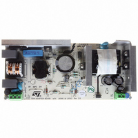
BOARD EVAL FOR L6566A
Manufacturer
STMicroelectronics
Type
Power Factor Correctionr
Datasheets
1.L6566ATR.pdf
(51 pages)
2.TSM1014IDT.pdf
(10 pages)
3.L6563ATR.pdf
(39 pages)
4.EVL6566A-75WADP.pdf
(8 pages)
Specifications of EVL6566A-75WADP
Main Purpose
AC/DC, Primary and Secondary Side with PFC
Outputs And Type
1, Isolated
Power - Output
75W
Voltage - Output
19V
Current - Output
4A
Voltage - Input
90 ~ 264VAC
Frequency - Switching
65kHz
Board Type
Fully Populated
Utilized Ic / Part
L6563, L6566A, TSM1014
Input Voltage
90 V to 264 V
Output Voltage
19 V
Dimensions
78 mm x 174 mm
Product
Power Management Modules
Lead Free Status / RoHS Status
Lead free / RoHS Compliant
Regulator Topology
-
Lead Free Status / Rohs Status
Lead free / RoHS Compliant
For Use With/related Products
L6563, L6566A
Other names
497-6449
Available stocks
Company
Part Number
Manufacturer
Quantity
Price


TSM1014
Therefore, for most adapter and battery charger applications, a quarter-watt, or half-watt resistor to make
the current sensing function is sufficient.
The current sinking outputs of the two trans-conductance operational amplifiers are common (to the
output of the IC). This makes an ORing function which ensures that whenever the current or the voltage
reaches too high values, the optocoupler is activated.
The relation between the controlled current and the controlled output voltage can be described with a
square characteristic as shown in the following V/I output-power graph.
Figure 3: Output Voltage versus Output Current
5.3 Compensation
The voltage-control trans-conductance operational amplifier can be fully compensated. Both its output
and negative input are directly accessible for external compensation components.
An example of a suitable voltage-control compensation network is shown in
consists of a capacitor Cvc1=2.2nF and a resistor Rcv1=22K
The current-control trans-conductance operational amplifier can be fully compensated. Both of its output
and negative input are directly accessible for external compensation components.
An example of a suitable current-control compensation network is also shown in
consists of a capacitor Cic1=2.2nF and a resistor Ric1=22K
5.4 Start-up and short circuit conditions
Under start-up or short-circuit conditions the TSM1014 is not provided with a high enough supply voltage.
This is due to the fact that the chip has its power supply line in common with the power supply line of the
system.
Therefore, the current limitation can only be ensured by the primary PWM module, which should be
chosen accordingly.
If the primary current limitation is considered not to be precise enough for the application, then a sufficient
supply for the TSM1014 has to be ensured under all conditions. For this, it would be necessary to add
some circuitry to supply the chip with a separate power line. This can be achieved in a number of ways,
including putting an additional winding on the transformer.
6/10
0
TSM1014 Vcc : independent power supply
Secondary current regulation
Vout
Voltage regulation
TSM1014 Vcc : On power output
Primary current regulation
Principles of Operation and Application Tips
in series.
in series.
Iout
Figure 2
Figure 2
on page 4. It
on page 4. It
Related parts for EVL6566A-75WADP
Image
Part Number
Description
Manufacturer
Datasheet
Request
R

Part Number:
Description:
BOARD DEMO FOR L6563/LL6566A
Manufacturer:
STMicroelectronics
Datasheet:

Part Number:
Description:
STMicroelectronics [RIPPLE-CARRY BINARY COUNTER/DIVIDERS]
Manufacturer:
STMicroelectronics
Datasheet:
Part Number:
Description:
STMicroelectronics [LIQUID-CRYSTAL DISPLAY DRIVERS]
Manufacturer:
STMicroelectronics
Datasheet:

Part Number:
Description:
BOARD EVAL FOR MEMS SENSORS
Manufacturer:
STMicroelectronics
Datasheet:
Part Number:
Description:
NPN TRANSISTOR POWER MODULE
Manufacturer:
STMicroelectronics
Datasheet:
Part Number:
Description:
TURBOSWITCH ULTRA-FAST HIGH VOLTAGE DIODE
Manufacturer:
STMicroelectronics
Datasheet:
Part Number:
Description:
Manufacturer:
STMicroelectronics
Datasheet:
Part Number:
Description:
DIODE / SCR MODULE
Manufacturer:
STMicroelectronics
Datasheet:
Part Number:
Description:
DIODE / SCR MODULE
Manufacturer:
STMicroelectronics
Datasheet:
Part Number:
Description:
Search -----> STE16N100
Manufacturer:
STMicroelectronics
Datasheet:
Part Number:
Description:
Search ---> STE53NA50
Manufacturer:
STMicroelectronics
Datasheet:
Part Number:
Description:
NPN Transistor Power Module
Manufacturer:
STMicroelectronics
Datasheet: