EVL6566A-75WADP STMicroelectronics, EVL6566A-75WADP Datasheet - Page 5
EVL6566A-75WADP
Manufacturer Part Number
EVL6566A-75WADP
Description
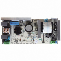
BOARD EVAL FOR L6566A
Manufacturer
STMicroelectronics
Type
Power Factor Correctionr
Datasheets
1.L6566ATR.pdf
(51 pages)
2.TSM1014IDT.pdf
(10 pages)
3.L6563ATR.pdf
(39 pages)
4.EVL6566A-75WADP.pdf
(8 pages)
Specifications of EVL6566A-75WADP
Main Purpose
AC/DC, Primary and Secondary Side with PFC
Outputs And Type
1, Isolated
Power - Output
75W
Voltage - Output
19V
Current - Output
4A
Voltage - Input
90 ~ 264VAC
Frequency - Switching
65kHz
Board Type
Fully Populated
Utilized Ic / Part
L6563, L6566A, TSM1014
Input Voltage
90 V to 264 V
Output Voltage
19 V
Dimensions
78 mm x 174 mm
Product
Power Management Modules
Lead Free Status / RoHS Status
Lead free / RoHS Compliant
Regulator Topology
-
Lead Free Status / Rohs Status
Lead free / RoHS Compliant
For Use With/related Products
L6563, L6566A
Other names
497-6449
Available stocks
Company
Part Number
Manufacturer
Quantity
Price


Principles of Operation and Application Tips
5
5.1 Voltage control
The voltage loop is controlled via a first trans-conductance operational amplifier, the resistor bridge R1,
R2, and the optocoupler which is directly connected to the output.
The relation between the values of R1 and R2 should be chosen as written in
where V
To avoid the discharge of the load, the resistor bridge R1, R2 should be highly resistive. For this type of
application, a total value of 100K
As an example, with R2 = 100K , V
Note that if the low drop diode is inserted between the load and the voltage regulation resistor bridge to
avoid current flowing from the load through the resistor bridge, this drop should be taken into account in
the above calculations by replacing V
5.2 Current control
The current loop is controlled via the second trans-conductance operational amplifier, the sense resistor
R
V
point is tied to the positive input of the current control operational amplifier, and its foot is to be connected
to lower potential point of the sense resistor as shown on the following figure. The resistors of this bridge
are matched to provide the best precision possible.
The control equation verifies:
where I
Note that the R
through it during full load operation.
sense
sense
Principles of Operation and Application Tips
, and the optocoupler.
threshold is achieved externally by a resistor bridge tied to the V
lim
out
is the desired limited current, and V
is the desired output voltage.
sense
resistor should be chosen taking into account the maximum dissipation (P
R1 = R2 x V
(or more) would be appropriate for the resistors R1 and R2.
out
out
V
I
R
lim
sense
= 4.10V, V
P
sense
by (V
lim
=
Ref
=
=
R
--------------------------------------- -
out
sense
5
/ (V
I
---------------------- -
I
+ V
lim
R
R
lim
Ref
V
R
5
4
out
is the threshold voltage for the current control loop.
ref
4
drop
+
) = 1.210V, then R1 = 41.9K .
=
V
+
- V
R
V
ref
V
R
).
5
sense
R
Ref
sense
5
sense
)
Ref
voltage reference. Its middle
Equation
1.
Equation 1
Equation 2
Equation 3
Equation 4
TSM1014
5/10
lim
)
Related parts for EVL6566A-75WADP
Image
Part Number
Description
Manufacturer
Datasheet
Request
R

Part Number:
Description:
BOARD DEMO FOR L6563/LL6566A
Manufacturer:
STMicroelectronics
Datasheet:

Part Number:
Description:
STMicroelectronics [RIPPLE-CARRY BINARY COUNTER/DIVIDERS]
Manufacturer:
STMicroelectronics
Datasheet:
Part Number:
Description:
STMicroelectronics [LIQUID-CRYSTAL DISPLAY DRIVERS]
Manufacturer:
STMicroelectronics
Datasheet:

Part Number:
Description:
BOARD EVAL FOR MEMS SENSORS
Manufacturer:
STMicroelectronics
Datasheet:
Part Number:
Description:
NPN TRANSISTOR POWER MODULE
Manufacturer:
STMicroelectronics
Datasheet:
Part Number:
Description:
TURBOSWITCH ULTRA-FAST HIGH VOLTAGE DIODE
Manufacturer:
STMicroelectronics
Datasheet:
Part Number:
Description:
Manufacturer:
STMicroelectronics
Datasheet:
Part Number:
Description:
DIODE / SCR MODULE
Manufacturer:
STMicroelectronics
Datasheet:
Part Number:
Description:
DIODE / SCR MODULE
Manufacturer:
STMicroelectronics
Datasheet:
Part Number:
Description:
Search -----> STE16N100
Manufacturer:
STMicroelectronics
Datasheet:
Part Number:
Description:
Search ---> STE53NA50
Manufacturer:
STMicroelectronics
Datasheet:
Part Number:
Description:
NPN Transistor Power Module
Manufacturer:
STMicroelectronics
Datasheet: