EVLVIP15L-5WSB STMicroelectronics, EVLVIP15L-5WSB Datasheet - Page 24
EVLVIP15L-5WSB
Manufacturer Part Number
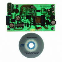
EVLVIP15L-5WSB
Description
EVAL BOARD FOR VIPER 15
Manufacturer
STMicroelectronics
Series
VIPer™ plusr
Type
AC/DC Switching Convertersr
Datasheet
1.VIPER15LN.pdf
(40 pages)
Specifications of EVLVIP15L-5WSB
Main Purpose
AC/DC, Primary Side
Board Type
Fully Populated
Utilized Ic / Part
VIPer15
Product
Power Management Modules
Lead Free Status / RoHS Status
Lead free / RoHS Compliant
Current - Output
-
Voltage - Output
-
Voltage - Input
-
Power - Output
-
Frequency - Switching
-
Outputs And Type
-
Regulator Topology
-
Lead Free Status / Rohs Status
Lead free / RoHS Compliant
For Use With/related Products
VIPER15LN
Other names
497-9083


Operation description
7.9
7.10
24/40
Starter
If the amplitude of the voltage on ZCD pin at the end of one oscillator cycle is smaller than
the V
system would stop.
This is what normally happens during converter’s power-up or under overload/short-circuit
conditions.
During the converter’s startup phase, the voltage on ZCD pin is not high enough to arm the
triggering circuit. Thus, the converter operates at a fixed frequency, F
on page 8
arm the ZCD circuit, MOSFET's turn-ON is locked to transformer demagnetization, hence
setting up quasi-resonant operation.
As protection, in case the ZCD voltage is permanently above the threshold V
switching frequency is reduced to the minimum value, F
page 8
Current limit set point and feed-forward option
The VIPER15 is a current mode converter and the drain current is limited cycle by cycle
according to the FB pin voltage value that is related with the feedback loop response and
the load. When the drain current, sensed by the integrated Sense-FET, reaches the current
limitation, after the internal propagation delay, the MOSFET is switched OFF. The current
limitation cannot exceed a certain value, I
sunk from the ZCD pin during MOSFET’s ON-time.
Usually a resistor, R
and then the peak drain current set-point: the lower the resistor is, the lower I
For a QR fly-back converter the power capability strongly depends on the input voltage. In
wide-range applications at maximum line the power capability can be more than twice the
value at minimum line, as shown by the upper curve in the diagram of
To reduce this dependence, the current limit I
increment of the input voltage, implementing the so called line feed-forward. It’s realized with
a resistor, R
on page 26
proportional to the input voltage through the auxiliary-to-primary turns ratio N
current proportional to the input voltage is sunk from the ZCD pin, thus lowering the
overcurrent set point.
ZCDAth
.
). As the voltage developed across the auxiliary winding becomes high enough to
. Since the voltage across the auxiliary winding during MOSFET’s on-time is
FF
arming threshold, in which case MOSFET's turn-ON could not be triggered, the
, connected between the ZCD pin and the auxiliary winding, see the
LIM
, connected from ZCD pin to ground is used to fix this sunk current
Doc ID 15455 Rev 5
Dlim
, that can be adjusted acting on the current
Dlim
has to be reduced according to the
OSCmin
, reported on
STARTER
Figure 31 on page 25
Table 8 on
ZCDAth
Dlim
AUX
(see
will be.
/N
Figure 32
VIPER15
Table 8
, the
P
, a
.
Related parts for EVLVIP15L-5WSB
Image
Part Number
Description
Manufacturer
Datasheet
Request
R

Part Number:
Description:
STMicroelectronics [RIPPLE-CARRY BINARY COUNTER/DIVIDERS]
Manufacturer:
STMicroelectronics
Datasheet:
Part Number:
Description:
STMicroelectronics [LIQUID-CRYSTAL DISPLAY DRIVERS]
Manufacturer:
STMicroelectronics
Datasheet:

Part Number:
Description:
BOARD EVAL FOR MEMS SENSORS
Manufacturer:
STMicroelectronics
Datasheet:
Part Number:
Description:
NPN TRANSISTOR POWER MODULE
Manufacturer:
STMicroelectronics
Datasheet:
Part Number:
Description:
TURBOSWITCH ULTRA-FAST HIGH VOLTAGE DIODE
Manufacturer:
STMicroelectronics
Datasheet:
Part Number:
Description:
Manufacturer:
STMicroelectronics
Datasheet:
Part Number:
Description:
DIODE / SCR MODULE
Manufacturer:
STMicroelectronics
Datasheet:
Part Number:
Description:
DIODE / SCR MODULE
Manufacturer:
STMicroelectronics
Datasheet:
Part Number:
Description:
Search -----> STE16N100
Manufacturer:
STMicroelectronics
Datasheet:
Part Number:
Description:
Search ---> STE53NA50
Manufacturer:
STMicroelectronics
Datasheet:
Part Number:
Description:
NPN Transistor Power Module
Manufacturer:
STMicroelectronics
Datasheet:
Part Number:
Description:
DIODE / SCR MODULE
Manufacturer:
STMicroelectronics
Datasheet: