EVLVIP15L-5WSB STMicroelectronics, EVLVIP15L-5WSB Datasheet - Page 23
EVLVIP15L-5WSB
Manufacturer Part Number
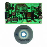
EVLVIP15L-5WSB
Description
EVAL BOARD FOR VIPER 15
Manufacturer
STMicroelectronics
Series
VIPer™ plusr
Type
AC/DC Switching Convertersr
Datasheet
1.VIPER15LN.pdf
(40 pages)
Specifications of EVLVIP15L-5WSB
Main Purpose
AC/DC, Primary Side
Board Type
Fully Populated
Utilized Ic / Part
VIPer15
Product
Power Management Modules
Lead Free Status / RoHS Status
Lead free / RoHS Compliant
Current - Output
-
Voltage - Output
-
Voltage - Input
-
Power - Output
-
Frequency - Switching
-
Outputs And Type
-
Regulator Topology
-
Lead Free Status / Rohs Status
Lead free / RoHS Compliant
For Use With/related Products
VIPER15LN
Other names
497-9083


VIPER15
7.8
Double blanking time
The blanking time, T
value) and the higher one is 6,3 μs (typical value). The value is linked to the voltage V
sampled during the time T
Section 7.11 on page 26
has the higher value if is detected V
page 23
The higher value of the blanking time is normally activated during the start-up phase or in
case of output short-circuit; when the output voltage of the converter is quite lower than the
regulated value. In this condition can happens that during the demagnetization of the
transformer, the V
V
higher frequency and in continuous mode. This false trigger is inhibited by the selection of
the higher value of T
During the normal operation, in steady state condition, the voltage V
demagnetization is higher than 1V and the selected T
Figure 30
Figure 30. Double T
(pin 3)
0.6V
T
ZCDTth
0.8V
Vaux
ZCD
T
ST RO BE
1V
BL ANK
A
C
F
D
0
) and the ZCD circuit can be erroneously trigged, leading the system to work at
.
shows the typical waveforms during the power up and the linked T
1. 5
6.3μs
ZCD
BLANK
BLANK
is very close to the arming and triggering thresholds (V
BLANK
). The time T
STROBE
, can have two different values: the lower one is 2,5 μs (typical
when V
4
Mosfet swit ched on by the starter
F
timing diagram
OSC
0. 5
Doc ID 15455 Rev 5
lim
defined as for the overvoltage protection (see the relevant
ZCD
ZCD
BLANK
is lower than 1 V.
> 1V, refer to
has the lower value if is detected V
BLANK
Table 8 on page 8
2.5μs
value is the lower one. The
Delay
Quasi Resonant Operation
Operation description
ZCD
and
during the
BLANK
Figure 30 on
ZCDAth
ZCD
selection.
< 1V or it
and
ZCD
23/40
t
t
t
t
t
t
t
t
,
Related parts for EVLVIP15L-5WSB
Image
Part Number
Description
Manufacturer
Datasheet
Request
R

Part Number:
Description:
STMicroelectronics [RIPPLE-CARRY BINARY COUNTER/DIVIDERS]
Manufacturer:
STMicroelectronics
Datasheet:
Part Number:
Description:
STMicroelectronics [LIQUID-CRYSTAL DISPLAY DRIVERS]
Manufacturer:
STMicroelectronics
Datasheet:

Part Number:
Description:
BOARD EVAL FOR MEMS SENSORS
Manufacturer:
STMicroelectronics
Datasheet:
Part Number:
Description:
NPN TRANSISTOR POWER MODULE
Manufacturer:
STMicroelectronics
Datasheet:
Part Number:
Description:
TURBOSWITCH ULTRA-FAST HIGH VOLTAGE DIODE
Manufacturer:
STMicroelectronics
Datasheet:
Part Number:
Description:
Manufacturer:
STMicroelectronics
Datasheet:
Part Number:
Description:
DIODE / SCR MODULE
Manufacturer:
STMicroelectronics
Datasheet:
Part Number:
Description:
DIODE / SCR MODULE
Manufacturer:
STMicroelectronics
Datasheet:
Part Number:
Description:
Search -----> STE16N100
Manufacturer:
STMicroelectronics
Datasheet:
Part Number:
Description:
Search ---> STE53NA50
Manufacturer:
STMicroelectronics
Datasheet:
Part Number:
Description:
NPN Transistor Power Module
Manufacturer:
STMicroelectronics
Datasheet:
Part Number:
Description:
DIODE / SCR MODULE
Manufacturer:
STMicroelectronics
Datasheet: