STEVAL-ISA011V1 STMicroelectronics, STEVAL-ISA011V1 Datasheet - Page 8
STEVAL-ISA011V1
Manufacturer Part Number
STEVAL-ISA011V1
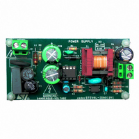
Description
BOARD EVAL VIPER12A LP AC/DC
Manufacturer
STMicroelectronics
Series
VIPER™r
Type
AC/DC Switching Convertersr
Specifications of STEVAL-ISA011V1
Design Resources
STEVAL-ISA011V1 Gerber Files STEVAL-ISA011V1 Schematic STEVAL-ISA011V1 Bill of Materials
Main Purpose
AC/DC, Primary Side
Outputs And Type
1, Isolated
Power - Output
4.1W
Voltage - Output
4.5V
Current - Output
900mA
Voltage - Input
88 ~ 265VAC
Regulator Topology
Flyback
Frequency - Switching
60kHz
Board Type
Fully Populated
Utilized Ic / Part
VIPer12A
Input Voltage
88 V to 265 V
Output Voltage
4.5 V
Product
Power Management Modules
Silicon Manufacturer
ST Micro
Silicon Core Number
VIPER12ADIP-E
Kit Application Type
Power Management - Voltage Regulator
Application Sub Type
AC / DC Adapter
Kit Contents
Board
Rohs Compliant
No
Lead Free Status / RoHS Status
Lead free / RoHS Compliant
For Use With/related Products
VIPer12A
Other names
497-6413
STEVAL-ISA011V1
STEVAL-ISA011V1
Available stocks
Company
Part Number
Manufacturer
Quantity
Price


STEVAL-ISA011V1 Board Design
1.2
8/33
The conduction losses in the main switch depend on the VIPer12A I
resistance, and are expressed as:
Equation 9
Where,
P
r
Secondary Side
In order to select the output rectifier (secondary) diode D
maximum reverse voltage that the diode has to sustain, as well as the average and root
mean square of the current flowing through it (see
page 30
Equation 10
Where,
V
V
V
V
A commonly used selection method is to choose a diode with a 40% to 50% safety margin
from the value given by the V
margin of 20% to 30% if a standard “fast” diode is used. The safety margin prevents diode
breakdown from oscillation caused by circuit parasitic elements (e.g. transformer secondary
inductance leakage or parasitic diode capacitance) when the MOSFET is turned ON.
If the calculated V
the D
excellent choice for this application.
ds(on)
OUT
VIPer12A
R(max)
R
DC(max)
= reflected voltage, and
11
= output voltage,
= VIPer12A ON resistance.
= maximum reverse voltage,
value is about 34V. This makes the STPS340U (with 40V breakdown voltage) an
). V
= selected maximum input voltage.
= VIPer12A conduction losses, and
R(max)
R(max)
is calculated as follows:
is 23V and a Schottky diode is used (adding a 50% safety margin),
V
P
R(max)
R max
VIPer12A
calculation when a Schottky diode is used, or a safety
=
Rev. 1
V
=
OUT
r
ds on
+
V
------------------
V
O UT
R
I
STEVAL-ISA011V1 Schematic on
2
PRMS m ax
V
DC m ax
11
, the designer needs to know the
AN2272 - Application Note
PRMS(max)
and ON
Related parts for STEVAL-ISA011V1
Image
Part Number
Description
Manufacturer
Datasheet
Request
R

Part Number:
Description:
BOARD RGB CTR ST7,STP08C596MTR
Manufacturer:
STMicroelectronics
Datasheet:

Part Number:
Description:
Power Management IC Development Tools Full Speed USB to RS232 Bridge Demo
Manufacturer:
STMicroelectronics
Datasheet:
Part Number:
Description:
Power Management IC Development Tools 2.5W solar eval BRD USB SPV1040 LD39050
Manufacturer:
STMicroelectronics
Datasheet:

Part Number:
Description:
BOARD EVAL FOR MEMS SENSORS
Manufacturer:
STMicroelectronics
Datasheet:

Part Number:
Description:
KIT DEV STARTER ST10F276Z5
Manufacturer:
STMicroelectronics
Datasheet:

Part Number:
Description:
BOARD EVAL HDMI $ VIDEO SWITCH
Manufacturer:
STMicroelectronics
Datasheet:

Part Number:
Description:
BOARD DEMO ACCELEROMETER DIL24
Manufacturer:
STMicroelectronics
Datasheet:

Part Number:
Description:
BOARD STLM75/STDS75/ST72F651
Manufacturer:
STMicroelectronics
Datasheet:

Part Number:
Description:
EVAL BOARD 3AXIS MEMS ACCELLRMTR
Manufacturer:
STMicroelectronics
Datasheet:

Part Number:
Description:
BOARD EVAL 8BIT MICRO + TDE1708
Manufacturer:
STMicroelectronics
Datasheet:
Part Number:
Description:
STMicroelectronics [RIPPLE-CARRY BINARY COUNTER/DIVIDERS]
Manufacturer:
STMicroelectronics
Datasheet:
Part Number:
Description:
STMicroelectronics [LIQUID-CRYSTAL DISPLAY DRIVERS]
Manufacturer:
STMicroelectronics
Datasheet:
Part Number:
Description:
BOARD EVAL FOR MEMS SENSORS
Manufacturer:
STMicroelectronics
Datasheet: