STEVAL-ISA011V1 STMicroelectronics, STEVAL-ISA011V1 Datasheet
STEVAL-ISA011V1
Specifications of STEVAL-ISA011V1
STEVAL-ISA011V1
Available stocks


Related parts for STEVAL-ISA011V1


STEVAL-ISA011V1 Summary of contents
Page 1
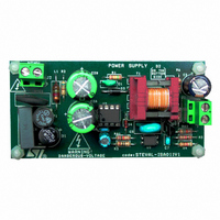
... This application note describes a low power, (output power of 4.1W) general purpose adapter which is able to handle a wide range input voltages (88V (Order Code STEVAL-ISA011V1) is based on the Viper12A monolithic device that has the power switch as well as the basic control function needed to implement a current mode flyback converter ...
Page 2
... Primary Side . . . . . . . . . . . . . . . . . . . . . . . . . . . . . . . . . . . . . . . . . . . . . . . . 5 1.1.1 1.1.2 1.2 Secondary Side . . . . . . . . . . . . . . . . . . . . . . . . . . . . . . . . . . . . . . . . . . . . . 8 1.2.1 1.2.2 1.2.3 1.3 Completed Transformer Design . . . . . . . . . . . . . . . . . . . . . . . . . . . . . . . . 12 1.4 Feedback Loop . . . . . . . . . . . . . . . . . . . . . . . . . . . . . . . . . . . . . . . . . . . . . 12 2 STEVAL-ISA011V1 Board Tests . . . . . . . . . . . . . . . . . . . . . . . . . . . . . . . 15 2.1 Start-up Tests . . . . . . . . . . . . . . . . . . . . . . . . . . . . . . . . . . . . . . . . . . . . . . 15 2.1.1 2.1.2 2.2 Temperature Tests . . . . . . . . . . . . . . . . . . . . . . . . . . . . . . . . . . . . . . . . . . 20 2.3 Dynamic Load Regulation Tests . . . . . . . . . . . . . . . . . . . . . . . . . . . . . . . . 20 2.4 Steady-State Tests . . . . . . . . . . . . . . . . . . . . . . . . . . . . . . . . . . . . . . . . . . 23 2.4.1 2.4.2 2.5 EMI Tests ...
Page 3
... Steady-state No Load 230V Figure 21. 115V Line Voltage Figure 22. 115V Line Neutral . . . . . . . . . . . . . . . . . . . . . . . . . . . . . . . . . . . . . . . . . . . . . . . . . . . . . . 28 AC Figure 23. 230V Line Voltage Figure 24. 230V Line Neutral . . . . . . . . . . . . . . . . . . . . . . . . . . . . . . . . . . . . . . . . . . . . . . . . . . . . . . 29 AC Figure 25. STEVAL-ISA011V1 Schematic . . . . . . . . . . . . . . . . . . . . . . . . . . . . . . . . . . . . . . . . . . . . . . 30 Waveforms . . . . . . . . . . . . . . . . . . . . . . . . . . . . . . . . . . . . . 24 AC Waveforms . . . . . . . . . . . . . . . . . . . . . . . . . . . . . . . . . . . . 24 AC Waveforms . . . . . . . . . . . . . . . . . . . . . . . . . . . . . . . . . . . . 25 AC Waveforms . . . . . . . . . . . . . . . . . . . . . . . . . . . . . . . . . . . . 25 AC Waveforms . . . . . . . . . . . . . . . . . . . . . . . . . . . . . . . . . . . . . 26 AC Waveforms . . . . . . . . . . . . . . . . . . . . . . . . . . . . . . . . . . . . 26 AC Waveforms . . . . . . . . . . . . . . . . . . . . . . . . . . . . . . . . . . . . 27 AC Waveforms . . . . . . . . . . . . . . . . . . . . . . . . . . . . . . . . . . . . 27 AC Rev. 1 ...
Page 4
List of Tables List of Tables Table 1. Electrical Characteristics . . . . . . . . . . . . . . . . . . . . . . . . . . . . . . ...
Page 5
... Equation ----------------------------------------------------------------- min pk value used is calculated Rev. 1 STEVAL-ISA011V1 Board Design Section 2.3: Dynamic STEVAL- is useful for this purpose – where P is the maximum output O O 5/33 ...
Page 6
... STEVAL-ISA011V1 Board Design An acceptable value for V Equation expressed as: Equation 3 Where the time between the two conduction cycles of the input bridge diodes, and f = line frequency. line The calculated value of C and C2b, see STEVAL-ISA011V Demo Board Schematic on page 30 This means that C electrolytic capacitor is usually around 20%. ...
Page 7
... This ensures MAX , the designer can calculate the ⇒ ------------------------ - PEAK PEAK expressed as, MAX ------------------------------------------------- - MAX ⇒ ------------------ - PRM S max PEAK 3 Rev. 1 STEVAL-ISA011V1 Board Design ⇒ 3mH, which is a little less P 258mA = P ⇒ D 0.42 = MAX ), which is the PRMS(max) I 97mA = PRMS max 7/33 ...
Page 8
... VIPer12A calculated as follows ------------------ = + R max OUT calculation when a Schottky diode is used safety R(max) is 23V and a Schottky diode is used (adding a 50% safety margin), R(max) Rev. 1 AN2272 - Application Note PRMS(max PRMS the designer needs to know the 11 STEVAL-ISA011V1 Schematic and ON ...
Page 9
... P = diode power dissipation, lossD V = drop voltage (when the diode is forward-biased diode average current, and D(avg dynamic resistance. dD Note: The formula and the correct values for V STEVAL-ISA011V1 Board Design is the output current while the cond – -------------------- - = DRMS PKS 3 (peak current at the secondary winding) can be calculated ...
Page 10
... STEVAL-ISA011V1 Board Design 1.2.2 Transformer Turns Ratio and D The turns ratio that is selected for the transformer depends on the output voltage, the chosen reflected voltage, and the average voltage drop across the output diode. Keeping in mind the voltage drop across its dynamic resistance, V ...
Page 11
... CAPRMS I = diode current root mean square, and DRMS I = output current. O The MBZ Type 1500 F 10V by RUBYCON capacitor was selected for this application. STEVAL-ISA011V1 Board Design , see STEVAL-ISA011V1 Schematic on page 300mV), and the ripple current ESR = -------------- - MAX I ...
Page 12
... STEVAL-ISA011V1 Board Design 1.3 Completed Transformer Design All of the calculations for the transformer design are complete. They include: Primary Inductance, Turns Ratio, and Winding Current Values (RMS, Average, and Peak). Notes order to prevent transformer saturation during the start-up phase, the current limit of the VIPer12A (I current ...
Page 13
... ESR. STEVAL-ISA011V1 Board Design ) to the feedback pin and ---------- = fly ---------------------------------------------------------------------------------- fly ESR + OUT STEVAL-ISA011V1 Schematic on page ------------------------------------------- - fly C ESR OUT OUT fly Rev. 1 values, fly ), and, typically, fly frequency. The last pole of the 13/33 ...
Page 14
... STEVAL-ISA011V1 Board Design Loop Gain crossover frequency is the last calculation required to define the compensation network. In this design, the crossover frequency selected is as high as 2.5kHz to provide the converter with good bandwidth. The Transfer Function output control is expressed as: Equation 23 Where VIPer12A feedback pin current, ...
Page 15
... AN2272 - Application Note 2 STEVAL-ISA011V1 Board Tests The tests performed with the STEVAL-ISA011V1 demo board are used to evaluate the converter behavior in terms of: efficiency, safe operating area of the devices, line regulation, and load regulation. 2.1 Start-up Tests The diagnostic board will handle a wide range of AC input voltage (88V its maximum output power is 4 ...
Page 16
... STEVAL-ISA011V1 Board Tests 2.1.1 Full Load Start-up Waveforms Figure 1 , Figure 2 that occur during the circuit start-up phase when Full Load condition, for the minimum (88V ), maximum (265V AC Figure 1. Full Load Start-up Waveforms at 88V Notes: Cyan/Blue (Ch2) = drain current, Green (Ch4) = output voltage, Magenta/Red (Ch3) = auxiliary output voltage for the VIPer12A self-supply (on V Yellow (Ch1) = drain voltage ...
Page 17
... Yellow (Ch1) = drain voltage. Figure 4. Full Load Start-up Waveforms at 230V Notes: Cyan/Blue (Ch2) = drain current, Green (Ch4) = output voltage, Magenta/Red (Ch3) = auxiliary output voltage for the VIPer12A self-supply (on V Yellow (Ch1) = drain voltage. STEVAL-ISA011V1 Board Tests Rev. 1 pin), and DD pin), and DD 17/33 ...
Page 18
... STEVAL-ISA011V1 Board Tests 2.1.2 No Load Start-up Waveforms Figure 5 , Figure 6 ( Section 2.1 they occur during the circuit start-up phase when no load is applied, for the minimum (88V Figure 5. No Load Start-up Waveforms at 88V Notes: Cyan/Blue (Ch2) = drain current, Green (Ch4) = output voltage, Magenta/Red (Ch3) = auxiliary output voltage for the VIPer12A self-supply (on V Yellow (Ch1) = drain voltage ...
Page 19
... Yellow (Ch1) = drain voltage. Figure 8. No Load Start-up Waveforms at 230V Notes: Cyan/Blue (Ch2) = drain current, Green (Ch4) = output voltage, Magenta/Red (Ch3) = auxiliary output voltage for the VIPer12A self-supply (on V Yellow (Ch1) = drain voltage. STEVAL-ISA011V1 Board Tests Rev. 1 pin), and DD pin), and DD 19/33 ...
Page 20
... STEVAL-ISA011V1 Board Tests 2.2 Temperature Tests These tests verify the board’s device and component temperatures. temperatures (the most stress measured, in terms of power dissipation) for the board’s main components. Note: The tests were performed at 25°C (ambient temperature), in Full Load conditions. ...
Page 21
... Notes: Magenta/Red (Ch3) = output voltage (set to 50mV/division), Yellow (Ch1) = VIPer12A feedback pin voltage, and Cyan/Blue (Ch2) = output (load) current. Figure 10. Step Load Change Stability Tests at 265V Notes: Magenta/Red (Ch3) = output voltage, Yellow (Ch1) = feedback pin voltage, and Cyan/Blue (Ch2) = output current. STEVAL-ISA011V1 Board Tests Rev. 1 21/33 ...
Page 22
... STEVAL-ISA011V1 Board Tests Figure 11. Step Load Change Stability Tests at 115V Notes: Magenta/Red (Ch3) = output voltage, Yellow (Ch1) = feedback pin voltage, and Cyan/Blue (Ch2) = output current. Figure 12. Step Load Change Stability Tests at 230V Notes: Magenta/Red (Ch3) = output voltage, Yellow (Ch1) = feedback pin voltage, and Cyan/Blue (Ch2) = output current ...
Page 23
... ( OUT 5.9 4.13 5.9 4.13 5.9 4.13 6.1 4.13 ) RMS 88V 115V 230V 265V Rev. 1 STEVAL-ISA011V1 Board Tests Table 4 ). The measurements include: ), maximum (265V ), and nominal input AC (W) V (V) O 4.59 4.59 4.59 4. Full Load O 210mV 214mV 215mV 220mV (%) ...
Page 24
... STEVAL-ISA011V1 Board Tests 2.4.1 Steady-State Full Load Waveforms Figure 13 and Figure 14 occur during converter steady-state testing when Full Load condition, for the minimum (88V ), maximum (265V AC Figure 13. Steady-state Full Load 88V Notes: Magenta/Red (Ch3) = output voltage, Green (Ch4) = drain voltage, and Cyan/Blue (Ch2) = drain current ...
Page 25
... Figure 15. Steady-state Full Load 115V Notes: Magenta/Red (Ch3) = output voltage, Green (Ch4) = drain voltage, and Cyan/Blue (Ch2) = drain current. Figure 16. Steady-state Full Load 230V Notes: Magenta/Red (Ch3) = output voltage, Green (Ch4) = drain voltage, and Cyan/Blue (Ch2) = drain current. STEVAL-ISA011V1 Board Tests Waveforms AC Waveforms AC Rev. 1 25/33 ...
Page 26
... STEVAL-ISA011V1 Board Tests 2.4.2 Steady-State No Load Waveforms Figure 17 and Figure 18 occur during converter steady-state testing when Load condition, for the minimum (88V ), maximum (265V AC Figure 17. Steady-state No Load 88V Notes: Magenta/Red (Ch3) = output voltage, Green (Ch4) = drain voltage, and Cyan/Blue (Ch2) = drain current. ...
Page 27
... Figure 19. Steady-state No Load 115V Notes: Magenta/Red (Ch3) = output voltage, Green (Ch4) = drain voltage, and Cyan/Blue (Ch2) = drain current. Figure 20. Steady-state No Load 230V Notes: Magenta/Red (Ch3) = output voltage, Green (Ch4) = drain voltage, and Cyan/Blue (Ch2) = drain current. STEVAL-ISA011V1 Board Tests Waveforms AC Waveforms AC Rev. 1 27/33 ...
Page 28
... STEVAL-ISA011V1 Board Tests 2.5 EMI Tests Pre-compliant tests with European Normative EN55022 for electromagnetic interference (EMI) were performed. illustrate that the conducted EMI induced by the converter to the main are below the normative limits. Figure 21 Note: through to 30MHz frequency range. Figure 21. 115V Figure 22 ...
Page 29
... AN2272 - Application Note Figure 23. 230V Figure 24. 230V Line Voltage AC Line Neutral AC Rev. 1 STEVAL-ISA011V1 Board Tests 29/33 ...
Page 30
... STEVAL-ISA011V Demo Board Schematic Appendix A STEVAL-ISA011V Demo Board Schematic Figure 25. STEVAL-ISA011V1 Schematic 30/ VDD Rev. 1 AN2272 - Application Note AI12225 ...
Page 31
... STTH1R06 STMicroelectronics Part D11 STPS340U (SMB Package) STMicroelectronics Part F1 250mA L12 1.5mH 0.25A NTC1 33 R1 12K 1/4W R2 10k R3 1.5k R4 10E 560 R7 12.5k 1% Precision Resistor R8 10k 1% Precision Resistor R9 56k T1 TDK SRW16ES_E44H013 U2 VIPer12A (ST Part) U3 TL1431 (ST Part) U4 PC817 Rev. 1 STEVAL-ISA011V1 Bill of Materials Value 31/33 ...
Page 32
Revision History 3 Revision History Table 7. Document revision history Date 2-February-2006 32/33 Revision 1 First edition Rev. 1 AN2272 - Application Note Changes ...
Page 33
... No license is granted by implication or otherwise under any patent or patent rights of STMicroelectronics. Specifications mentioned in this publication are subject to change without notice. This publication supersedes and replaces all information previously supplied. STMicroelectronics products are not authorized for use as critical components in life support devices or systems without express written approval of STMicroelectronics ...