NCP1230GEVB ON Semiconductor, NCP1230GEVB Datasheet - Page 5
NCP1230GEVB
Manufacturer Part Number
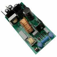
NCP1230GEVB
Description
EVAL BOARD FOR NCP1230G
Manufacturer
ON Semiconductor
Specifications of NCP1230GEVB
Design Resources
NCP1230 EVB BOM NCP1230GEVB Gerber Files NCP1230 EVB Schematic
Main Purpose
AC/DC, Primary Side
Outputs And Type
1, Isolated
Power - Output
90W
Voltage - Output
18.6V
Current - Output
4.74A
Voltage - Input
85 ~ 265VAC
Regulator Topology
Flyback
Frequency - Switching
47kHz
Board Type
Fully Populated
Utilized Ic / Part
NCP1230
Lead Free Status / RoHS Status
Lead free / RoHS Compliant
For Use With/related Products
NCP1230G
Other names
NCP1230GEVBOS


Overtemperature Protection
shutdown, the Zener diode can be replaced by an NTC (refer
to Figure 3), or an NTC can be placed in parallel with the
Zener diode to have OVP and OTP protection. When an
overtemperature condition occurs, the resistance of the NTC
will decrease, allowing current to flow through the PNP
transistor biasing up the Current Sense pin.
Slope Compensation
mode with a duty cycle greater than 50% requires slope
compensation. In this application the power supply will
always be operating in the discontinuous mode, so no slope
compensation is required.
suppressing the leading edge of the current signal. Typically,
the leading edge of the current will have a large spike due to
the transformer leakage inductance. If the spike is not
filtered, it can prematurely turn off the MOSFET. The
NCP1230 does have a leading edge blanking circuit, but it
is a good design practice to add an external filter. The time
constant of the filter must be significantly higher than the
highest expected operating frequency, but low enough to
filter the spike.
Output Control
there must be at least 45 of phase margin when the loop gain
crosses cross zero dB. The following equations derive the
Flyback converter transfer function while operating in the
discontinuous continuous mode.
Where:
To implement Overtemperature Protection (OTP)
A Flyback converter operating in continuous conduction
The resistor R21 and capacitor C24 form a low pass filter
Feedback theory states that for the control loop to be stable
Po is the maximum output power
Vo is the output voltage
Ro is the output resistance
Figure 3. Overtemperature Protection Circuit
R26
10 k
Vaux
100 pF
MMBT2907A/SOT
Q3
NTC
C24
P + 1
Po + Vo
2
· Ipk 2 · Lp · f
Ro
2
1
2
3
4
1 k
GTS
FB
CS
GND
NCP1230
VCC
DRV
HV
Rsense
8
6
5
http://onsemi.com
AND8154/D
5
Where:
Where:
the output capacitor(s) and the load resistors. In this
application there are four 2200 mF capacitors in parallel:
the control loop because we are sensing the output voltage
before the LC network.
output capacitor(s) and the capacitors esr. The esr of each
capacitors is 0.022 W (from the data sheet).
feedback pin to ground to reduce the switching noise on the
feedback pin. Care must be taken not to have too large a
capacitor, or a low frequency pole may be created in the
feedback loop.
Output Voltage Regulation
TL431 on the secondary side of the transformer. The output
voltage is sensed and divided down to the reference level of
the TL431 (2.5 V typical) by the resistive divider network
consisting of R4 and R10.
I is the peak primary current
Lp is the transformer primary inductance
F is the switching frequency of the controller
Ip is the peak primary current
Rs is the current sense resistor
Vc is the control voltage
3, the feedback input voltage is divided down by a factor
of three
Combining equations the open loop gain is:
With current mode control, there is pole associated with
The secondary filter made up of L1 and C8 does not affect
In addition to the pole, there is a zero associated with the
A small 0.47 nF capacitor (C25) is connected from the
The output voltage regulation is achieved by using a
fz +
fp +
Vo
Vc
2pCo · esr
+
pCoRo
1
Vo
Vo
i
i
1
Vo 2
Ro
Ro · Lp · f
+
+
i + Ipk @ Rs + Vc
Vc + 3 @ Rs @ Ipk
i + Ip · Rs + Vc
+
+ 1
+
2
6.28 · 8800 ·
Ro · f · Lp
Ro · Lp · f
2
p · 8800 · 3.9
· Ipk 2 · Lp · f
2
2
· n · d · Ipk · Rs · 3
1
1
3
· n · d
· n · d
3
0.022
+ 9.3 Hz
4
+ 3.3 kHz
Related parts for NCP1230GEVB
Image
Part Number
Description
Manufacturer
Datasheet
Request
R

Part Number:
Description:
Fixed Frequency Controller Featuring Pfc Go To Standby Function
Manufacturer:
ON Semiconductor
Datasheet:
Part Number:
Description:
ON Semiconductor [VOLTAGE REGULATOR]
Manufacturer:
ON Semiconductor
Datasheet:
Part Number:
Description:
357-036-542-201 CARDEDGE 36POS DL .156 BLK LOPRO
Manufacturer:
ON Semiconductor
Datasheet:
Part Number:
Description:
357-036-542-201 CARDEDGE 36POS DL .156 BLK LOPRO
Manufacturer:
ON Semiconductor
Datasheet:
Part Number:
Description:
357-036-542-201 CARDEDGE 36POS DL .156 BLK LOPRO
Manufacturer:
ON Semiconductor
Datasheet:
Part Number:
Description:
357-036-542-201 CARDEDGE 36POS DL .156 BLK LOPRO
Manufacturer:
ON Semiconductor
Datasheet:
Part Number:
Description:
357-036-542-201 CARDEDGE 36POS DL .156 BLK LOPRO
Manufacturer:
ON Semiconductor
Datasheet:
Part Number:
Description:
357-036-542-201 CARDEDGE 36POS DL .156 BLK LOPRO
Manufacturer:
ON Semiconductor
Datasheet:
Part Number:
Description:
357-036-542-201 CARDEDGE 36POS DL .156 BLK LOPRO
Manufacturer:
ON Semiconductor
Datasheet:
Part Number:
Description:
357-036-542-201 CARDEDGE 36POS DL .156 BLK LOPRO
Manufacturer:
ON Semiconductor
Datasheet:
Part Number:
Description:
357-036-542-201 CARDEDGE 36POS DL .156 BLK LOPRO
Manufacturer:
ON Semiconductor
Datasheet:
Part Number:
Description:
357-036-542-201 CARDEDGE 36POS DL .156 BLK LOPRO
Manufacturer:
ON Semiconductor
Datasheet:
Part Number:
Description:
Manufacturer:
ON Semiconductor
Datasheet:
Part Number:
Description:
Manufacturer:
ON Semiconductor
Datasheet: