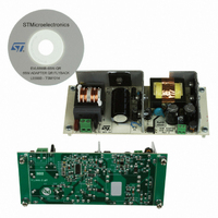
EVL6566B-65W-QR STMicroelectronics, EVL6566B-65W-QR Datasheet - Page 22

EVL6566B-65W-QR
Manufacturer Part Number
EVL6566B-65W-QR
Description
BOARD EVAL SMPS FOR L6566B
Manufacturer
STMicroelectronics
Type
Power Factor Correctionr
Specifications of EVL6566B-65W-QR
Main Purpose
AC/DC, Primary Side
Outputs And Type
1, Isolated
Power - Output
65W
Voltage - Output
700V
Voltage - Input
8 ~ 23 V
Regulator Topology
Flyback
Frequency - Switching
100kHz
Board Type
Fully Populated
Utilized Ic / Part
L6566B
Input Voltage
90 V to 265 V
Output Voltage
1.8 V to 12 V
Board Size
150 mm x 75 mm
Product
Power Management Modules
Dimensions
150 mm x 75 mm
Lead Free Status / RoHS Status
Lead free by exemption / RoHS compliant by exemption
Current - Output
-
Lead Free Status / Rohs Status
Lead free / RoHS Compliant
For Use With/related Products
L6566B
Other names
497-10165
3.7
22/34
Functional checking
Figure 30. EVL6566B-40WSTB OVP at
CH1: Vdrain
CH2: L6566B VCC
CH3: +12 V
CH4: +1.8 V
Overvoltage protection (OVP)
A protection that any power supply must have is that against the failure of the feedback
circuitry. If this occurs, the SMPS output voltages can rise to high values, depending on the
load on each output and the transformer coupling between the windings. To avoid this kind
of failure an innovative protection has been integrated in the L6566B sensing the auxiliary
winding voltage. This signal is connected to the L6566B at the ZCD (pin#11) through a
simple divider setting the threshold level. Once the ZCD pin voltage becomes higher than
the 5 V internal threshold, the IC is latched. This feature properly protects the power supply
from OVP and stops the operation from decreasing consumption at a low value. The status
is latched until Vcc falls below the UVLO threshold. To remain in the latched status the
L6566B internal HV generator is activated periodically so that Vcc oscillates between the
startup threshold VccON and VccON - 0.5 V. The SMPS can restart after the disconnection
of the converter from the mains and the Vcc pin decreases below the UVLO threshold. In
Figure 30
conditions. The maximum voltage values on each output are also shown and as visible there
is just a slight variation between the two load conditions.
230 Vac- full load
and 31, the circuit behavior is shown as described above at full-load and no-load
Doc ID 14630 Rev 2
Figure 31. EVL6566B-40WSTB OVP at 230 Vac-
CH1: Vdrain
CH2: L6566B VCC
CH3: +12 V
CH4: +1.8 V
no load
AN2749


