EVL6566B-65W-QR STMicroelectronics, EVL6566B-65W-QR Datasheet - Page 13
EVL6566B-65W-QR
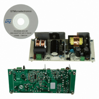
Manufacturer Part Number
EVL6566B-65W-QR
Description
BOARD EVAL SMPS FOR L6566B
Manufacturer
STMicroelectronics
Type
Power Factor Correctionr
Specifications of EVL6566B-65W-QR
Main Purpose
AC/DC, Primary Side
Outputs And Type
1, Isolated
Power - Output
65W
Voltage - Output
700V
Voltage - Input
8 ~ 23 V
Regulator Topology
Flyback
Frequency - Switching
100kHz
Board Type
Fully Populated
Utilized Ic / Part
L6566B
Input Voltage
90 V to 265 V
Output Voltage
1.8 V to 12 V
Board Size
150 mm x 75 mm
Product
Power Management Modules
Dimensions
150 mm x 75 mm
Lead Free Status / RoHS Status
Lead free by exemption / RoHS compliant by exemption
Current - Output
-
Lead Free Status / Rohs Status
Lead free / RoHS Compliant
For Use With/related Products
L6566B
Other names
497-10165


AN2749
Figure 6.
CH1: Vdrain
CH2: L6566B VGate
CH3: L6566B VComp
If the load is further decreased, the L6566B works in burst mode. Once the COMP (pin#9)
voltage drops below the internal threshold, the L6566B stops the gate driver operation
decreasing the internal circuitry consumption to minimize C19 discharging. Once the comp
voltage rises above the internal burst mode threshold the device restarts switching. In
Figure 8
because at no-load condition the auxiliary voltage powering the L6566B falls at input mains
increasing. This very often causes the supply voltage Vcc of the control IC to drop below the
UVLO threshold so that the operation becomes intermittent, which is undesired.
Furthermore, this must be traded off against the need of generating a voltage not exceeding
the maximum allowed by the control IC at full load to avoid overstress to the internal Vcc pin
clamping circuitry and consequent overheating of the controller.
To overcome this problem, the device, besides reducing its own consumption during burst-
mode operation, also features a proprietary adaptive UVLO function. It consists of shifting
the UVLO threshold downwards at light load, namely when the voltage at pin COMP falls
below a threshold VCOMPO internally fixed, so as to have a greater margin. To prevent any
malfunction during transients from minimum to maximum load the normal (higher) UVLO
threshold is re-established when the voltage at pin COMP exceeds VCOMPL and Vcc has
exceeded the normal UVLO threshold. The normal UVLO threshold ensures that at full load
the MOSFET is driven with a proper gate-to-source voltage. As visible in
measured showing that there is a good margin with respect to the maximum turnoff
threshold (8 V maximum) of the L6566B.
EVL6566B-40WSTB waveforms at
230 V - Pin=30 W
and
9
the burst-mode waveforms are shown. The pictures are taken at 265 V
Doc ID 14630 Rev 2
Figure 7.
CH1: Vdrain
CH2: L6566B VGate
CH3: L6566B VComp
EVL6566B-40WSTB waveforms at
230 V - Pin=4 W
Functional checking
Figure 9
the Vcc is
13/34
Related parts for EVL6566B-65W-QR
Image
Part Number
Description
Manufacturer
Datasheet
Request
R

Part Number:
Description:
BOARD EVAL FOR L6566B
Manufacturer:
STMicroelectronics
Datasheet:

Part Number:
Description:
BOARD EVAL FOR L6566B
Manufacturer:
STMicroelectronics
Datasheet:

Part Number:
Description:
BOARD EVAL FOR L6566B
Manufacturer:
STMicroelectronics
Datasheet:

Part Number:
Description:
Power Management Modules & Development Tools L6566B-60WQR Eval Board
Manufacturer:
STMicroelectronics
Part Number:
Description:
STMicroelectronics [RIPPLE-CARRY BINARY COUNTER/DIVIDERS]
Manufacturer:
STMicroelectronics
Datasheet:
Part Number:
Description:
STMicroelectronics [LIQUID-CRYSTAL DISPLAY DRIVERS]
Manufacturer:
STMicroelectronics
Datasheet:

Part Number:
Description:
BOARD EVAL FOR MEMS SENSORS
Manufacturer:
STMicroelectronics
Datasheet:
Part Number:
Description:
NPN TRANSISTOR POWER MODULE
Manufacturer:
STMicroelectronics
Datasheet:
Part Number:
Description:
TURBOSWITCH ULTRA-FAST HIGH VOLTAGE DIODE
Manufacturer:
STMicroelectronics
Datasheet:
Part Number:
Description:
Manufacturer:
STMicroelectronics
Datasheet:
Part Number:
Description:
DIODE / SCR MODULE
Manufacturer:
STMicroelectronics
Datasheet:
Part Number:
Description:
DIODE / SCR MODULE
Manufacturer:
STMicroelectronics
Datasheet: