STEVAL-ISA051V1 STMicroelectronics, STEVAL-ISA051V1 Datasheet - Page 23
STEVAL-ISA051V1
Manufacturer Part Number
STEVAL-ISA051V1
Description
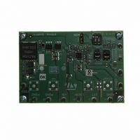
BOARD EVAL PM6670S DDR2/3
Manufacturer
STMicroelectronics
Type
DC/DC Switching Converters, Regulators & Controllersr
Specifications of STEVAL-ISA051V1
Design Resources
STEVAL-ISA051V1 Gerber Files STEVAL-ISA051V1 Schematic STEVAL-ISA051V1 Bill of Material
Main Purpose
Special Purpose DC/DC, DDR Memory Supply
Outputs And Type
4, Non-Isolated
Voltage - Output
1.5V, 1.8V
Voltage - Input
4.5 ~ 28V
Regulator Topology
Buck
Board Type
Fully Populated
Utilized Ic / Part
PM6670
Input Voltage
4.5 V to 28 V
Output Voltage
1.8 V, 1.5 V
Product
Power Management Modules
Silicon Manufacturer
ST Micro
Silicon Core Number
PM6670S
Kit Application Type
Power Management
Application Sub Type
DDR2/3 Memory Power Supply Controller
Kit Contents
Board
Lead Free Status / RoHS Status
Lead free / RoHS Compliant
Current - Output
-
Power - Output
-
Frequency - Switching
-
Lead Free Status / Rohs Status
Lead free / RoHS Compliant
For Use With/related Products
PM6670S
Other names
497-8411
Available stocks
Company
Part Number
Manufacturer
Quantity
Price
Company:

Part Number:
STEVAL-ISA051V1
Manufacturer:
STMicroelectronics
Quantity:
1


PM6670S
7.1.1
Figure 30. Switching section simplified block diagram
Constant-on-time architecture
Figure 30
The switching regulator of the PM6670S owns a one-shot generator that ignites the high-
side MOSFET when the following conditions are simultaneously satisfied: the PWM
comparator is high (i.e. output voltage is lower than Vr = 0.9 V), the synchronous rectifier
current is below the current limit threshold and the minimum off-time has expired.
A minimum off-time constraint (300 ns typ.) is introduced to assure the boot capacitor
charge and allow inductor valley current sensing on low-side MOSFET. A minimum on-time
is also introduced to assure the start-up switching sequence.
Once the on-time has timed out, the high side switch is turned off, while the synchronous
rectifier is ignited according to the anti-cross conduction management circuitry.
When the output voltage reaches the valley limit (determined by internal reference
Vr = 0.9 V), the low-side MOSFET is turned off according to the anti-cross conduction logic
once again, and a new cycle begins.
shows the simplified block diagram of the constant-on-time controller.
Doc ID 14432 Rev 4
Device description
23/54
Related parts for STEVAL-ISA051V1
Image
Part Number
Description
Manufacturer
Datasheet
Request
R

Part Number:
Description:
BOARD RGB CTR ST7,STP08C596MTR
Manufacturer:
STMicroelectronics
Datasheet:

Part Number:
Description:
Power Management IC Development Tools Full Speed USB to RS232 Bridge Demo
Manufacturer:
STMicroelectronics
Datasheet:
Part Number:
Description:
Power Management IC Development Tools 2.5W solar eval BRD USB SPV1040 LD39050
Manufacturer:
STMicroelectronics
Datasheet:

Part Number:
Description:
BOARD EVAL FOR MEMS SENSORS
Manufacturer:
STMicroelectronics
Datasheet:

Part Number:
Description:
KIT DEV STARTER ST10F276Z5
Manufacturer:
STMicroelectronics
Datasheet:

Part Number:
Description:
BOARD EVAL HDMI $ VIDEO SWITCH
Manufacturer:
STMicroelectronics
Datasheet:

Part Number:
Description:
BOARD DEMO ACCELEROMETER DIL24
Manufacturer:
STMicroelectronics
Datasheet:

Part Number:
Description:
BOARD STLM75/STDS75/ST72F651
Manufacturer:
STMicroelectronics
Datasheet:

Part Number:
Description:
EVAL BOARD 3AXIS MEMS ACCELLRMTR
Manufacturer:
STMicroelectronics
Datasheet:

Part Number:
Description:
BOARD EVAL 8BIT MICRO + TDE1708
Manufacturer:
STMicroelectronics
Datasheet:
Part Number:
Description:
STMicroelectronics [RIPPLE-CARRY BINARY COUNTER/DIVIDERS]
Manufacturer:
STMicroelectronics
Datasheet:
Part Number:
Description:
STMicroelectronics [LIQUID-CRYSTAL DISPLAY DRIVERS]
Manufacturer:
STMicroelectronics
Datasheet:
Part Number:
Description:
BOARD EVAL FOR MEMS SENSORS
Manufacturer:
STMicroelectronics
Datasheet: