STEVAL-ISA019V2 STMicroelectronics, STEVAL-ISA019V2 Datasheet - Page 6
STEVAL-ISA019V2
Manufacturer Part Number
STEVAL-ISA019V2
Description
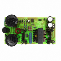
BOARD EVAL SMPS L6565 3PHASE APP
Manufacturer
STMicroelectronics
Type
Motor / Motion Controllers & Driversr
Specifications of STEVAL-ISA019V2
Mfg Application Notes
L6565/STC04IE170HV AppNote
Main Purpose
AC/DC, Primary Side
Outputs And Type
1, Isolated
Power - Output
80W
Voltage - Output
24V
Current - Output
3.33A
Voltage - Input
250 ~ 850V
Regulator Topology
Flyback
Board Type
Fully Populated
Utilized Ic / Part
L6565, STC04IE170HV
Input Voltage
250 V to 850 V
Output Voltage
24 V
Product
Power Management Modules
Lead Free Status / RoHS Status
Lead free / RoHS Compliant
Frequency - Switching
-
Lead Free Status / Rohs Status
Lead free / RoHS Compliant
For Use With/related Products
L6565, STC04IE170HV
Other names
497-6339


6/34
Flyback stage design
As commonly known, the voltage stress on the device (power switch) is given by:
Equation 1
where V
allowed by the clamping network. It has been set at 200 V. N
primary side, while N
Taking into account a 200 V margin, the maximum flyback voltage that can be chosen is:
Equation 2
After calculating the flyback voltage, proceed with the next step in the converter design.
The turn ratio between primary and secondary side is calculated with the following formula:
Equation 3
As a first approximation, since the turn-on of the device occurs immediately after the energy
stored on the primary side inductance has been totally transferred to the secondary side:
Equation 4
and
Equation 5
where T
transformer inductance and T
Combining the two previous equations, T
Equation 6
The next step is to calculate the peak current. According to the converter specification in
Table
does not take into account the losses on the power switch, on the input bridge, and on the
rectified network, we have:
Equation 7
1, output power of 80 W and desired efficiency (at least 80%), by using a formula that
onmax
fl
= flyback voltage = (V
V
is the maximum on time, T
fl
=
BV V
s
–
is the number of turns on the main output secondary winding.
inmax
P
IN
N
------ -
N
=
S
–
p
s
Doc ID 13127 Rev 4
out
is the switching time.
1.25P
V
T
V
=
spike
onmax
off
V
+ V
--------------------------------------- -
V
dcmin
out
T
=
OUT
F
onmax
–
, diode)*N
V
+
V
=
T
inmax
V
reset
=
onmax
m
V
onmax
fl
------------------------------ -
V
F diode
arg
1
-- - L
2
----------------------- -
,
dcmin
+
V
•
in
is the time needed to demagnetize the
T
fl
–
T
=
reset
•
is:
V
S
P
=
p
T
I
fl
1700 1000 200
=
+
/N
P
S
–
V
V
2
=
--------------- -
24
=
s
fl
V
fl
250
T
and V
T
spike
≅
–
+
1
-- - V
2
---------------------------------------------- -
reset
S
10μs
1
dcmin
=
spike
10
L
–
P
p
2
T
T
is the number of turns on the
S
is the maximum overvoltage
onmax
–
250
2
=
250V
AN2495
Related parts for STEVAL-ISA019V2
Image
Part Number
Description
Manufacturer
Datasheet
Request
R

Part Number:
Description:
BOARD RGB CTR ST7,STP08C596MTR
Manufacturer:
STMicroelectronics
Datasheet:

Part Number:
Description:
Power Management IC Development Tools Full Speed USB to RS232 Bridge Demo
Manufacturer:
STMicroelectronics
Datasheet:
Part Number:
Description:
Power Management IC Development Tools 2.5W solar eval BRD USB SPV1040 LD39050
Manufacturer:
STMicroelectronics
Datasheet:

Part Number:
Description:
BOARD EVAL FOR MEMS SENSORS
Manufacturer:
STMicroelectronics
Datasheet:

Part Number:
Description:
KIT DEV STARTER ST10F276Z5
Manufacturer:
STMicroelectronics
Datasheet:

Part Number:
Description:
BOARD EVAL HDMI $ VIDEO SWITCH
Manufacturer:
STMicroelectronics
Datasheet:

Part Number:
Description:
BOARD DEMO ACCELEROMETER DIL24
Manufacturer:
STMicroelectronics
Datasheet:

Part Number:
Description:
BOARD STLM75/STDS75/ST72F651
Manufacturer:
STMicroelectronics
Datasheet:

Part Number:
Description:
EVAL BOARD 3AXIS MEMS ACCELLRMTR
Manufacturer:
STMicroelectronics
Datasheet:

Part Number:
Description:
BOARD EVAL 8BIT MICRO + TDE1708
Manufacturer:
STMicroelectronics
Datasheet:
Part Number:
Description:
STMicroelectronics [RIPPLE-CARRY BINARY COUNTER/DIVIDERS]
Manufacturer:
STMicroelectronics
Datasheet:
Part Number:
Description:
STMicroelectronics [LIQUID-CRYSTAL DISPLAY DRIVERS]
Manufacturer:
STMicroelectronics
Datasheet:
Part Number:
Description:
BOARD EVAL FOR MEMS SENSORS
Manufacturer:
STMicroelectronics
Datasheet: