STEVAL-ISA019V2 STMicroelectronics, STEVAL-ISA019V2 Datasheet - Page 13
STEVAL-ISA019V2
Manufacturer Part Number
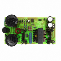
STEVAL-ISA019V2
Description
BOARD EVAL SMPS L6565 3PHASE APP
Manufacturer
STMicroelectronics
Type
Motor / Motion Controllers & Driversr
Specifications of STEVAL-ISA019V2
Mfg Application Notes
L6565/STC04IE170HV AppNote
Main Purpose
AC/DC, Primary Side
Outputs And Type
1, Isolated
Power - Output
80W
Voltage - Output
24V
Current - Output
3.33A
Voltage - Input
250 ~ 850V
Regulator Topology
Flyback
Board Type
Fully Populated
Utilized Ic / Part
L6565, STC04IE170HV
Input Voltage
250 V to 850 V
Output Voltage
24 V
Product
Power Management Modules
Lead Free Status / RoHS Status
Lead free / RoHS Compliant
Frequency - Switching
-
Lead Free Status / Rohs Status
Lead free / RoHS Compliant
For Use With/related Products
L6565, STC04IE170HV
Other names
497-6339


AN2495
During the conduction time, the junction base-emitter of the ESBT can be seen as a
forward-biased diode. To complete the secondary side load loop, the voltage drop on both
diode D and resistor RB must be added in series with the base of the ESBT. The equivalent
secondary side voltage source is given by:
Equation 22
Since the magnetization inductance cannot be neglected, only I
collector current, is transferred to the secondary. As a result, the magnetization current has
to be first as low as possible. Meanwhile, the value of the magnetization inductance must be
taken into account for the proper calculation of transformer primary turns and turns ratio.
The magnetization voltage drop, that is, the voltage at the primary of the current transformer,
can now be easily calculated:
Equation 23
The magnetization current will be:
Equation 24
The number of primary turns should be increased if I
have a window area large enough to hold all primary and secondary windings. Otherwise it
is necessary to choose a bigger core size. Once both core material and size are fixed, the
turn ratio must be adjusted to get the desiderated I
Equation 25
where I
The insulation between primary and secondary should be considered since the voltage on
the primary side during the off time can surpass 1500 V.
The next step is to select the Zener diode, the capacitor C
performance of the ESBT is related to the initial base peak current and its duration t
which is given approximately by
Equation 26
A suitable value for R
peak, and at the same time, it generates negligible power dissipation.
The value t
frequency. Bear in mind that in practical applications, it should never be lower than 200 ns.
The value of C
Mmax
peak
is the maximum magnetization current.
b
can be determined once the minimum ON time is set based on the operating
can be counted since the values of t
b
is 0.56 Ω. It can eliminate the ringing on the base current after the
Doc ID 13127 Rev 4
V
V
Equation
N
1
S
eff
=
=
I
V
=
Mmax
V
S
t
BEon
I
---- -
I
peak
P
B
•
=
N
--------- -
N
26:
1T
2T
=
I
------------------------------------
–
Cmax
=
=
V
--------------------------- -
V
3R
1
D
2.5
T
L
–
I
---- -
ONmax
–
5
C
b
TP
V
C
C
I
•
Mmax
RB
/I
b
1
-- -
5
peak
Mmax
B
=
≅
ratio according to
0.5 V
2.5V
and R
b
is relatively high. The core must
, and the resistor R
( )
Base driving circuit design
b
P
, a fraction of the total
are known.
Equation 25
b
. The turn-on
peak
below:
13/34
,
Related parts for STEVAL-ISA019V2
Image
Part Number
Description
Manufacturer
Datasheet
Request
R

Part Number:
Description:
BOARD RGB CTR ST7,STP08C596MTR
Manufacturer:
STMicroelectronics
Datasheet:

Part Number:
Description:
Power Management IC Development Tools Full Speed USB to RS232 Bridge Demo
Manufacturer:
STMicroelectronics
Datasheet:
Part Number:
Description:
Power Management IC Development Tools 2.5W solar eval BRD USB SPV1040 LD39050
Manufacturer:
STMicroelectronics
Datasheet:

Part Number:
Description:
BOARD EVAL FOR MEMS SENSORS
Manufacturer:
STMicroelectronics
Datasheet:

Part Number:
Description:
KIT DEV STARTER ST10F276Z5
Manufacturer:
STMicroelectronics
Datasheet:

Part Number:
Description:
BOARD EVAL HDMI $ VIDEO SWITCH
Manufacturer:
STMicroelectronics
Datasheet:

Part Number:
Description:
BOARD DEMO ACCELEROMETER DIL24
Manufacturer:
STMicroelectronics
Datasheet:

Part Number:
Description:
BOARD STLM75/STDS75/ST72F651
Manufacturer:
STMicroelectronics
Datasheet:

Part Number:
Description:
EVAL BOARD 3AXIS MEMS ACCELLRMTR
Manufacturer:
STMicroelectronics
Datasheet:

Part Number:
Description:
BOARD EVAL 8BIT MICRO + TDE1708
Manufacturer:
STMicroelectronics
Datasheet:
Part Number:
Description:
STMicroelectronics [RIPPLE-CARRY BINARY COUNTER/DIVIDERS]
Manufacturer:
STMicroelectronics
Datasheet:
Part Number:
Description:
STMicroelectronics [LIQUID-CRYSTAL DISPLAY DRIVERS]
Manufacturer:
STMicroelectronics
Datasheet:
Part Number:
Description:
BOARD EVAL FOR MEMS SENSORS
Manufacturer:
STMicroelectronics
Datasheet: