RDK-115 Power Integrations, RDK-115 Datasheet
RDK-115
Specifications of RDK-115


Related parts for RDK-115


RDK-115 Summary of contents
Page 1
... Reference Design Report for a 7.5 W Title Continuous Peak DVD / Set Top Box Using TNY376PN 85–265 VAC Input, 3.3 V (500 mA (500 mA), Specification 12 V (250 mA) and –12 V (30 mA) Outputs DVD / Set Top Box Application Power Integrations Applications Department Author Document RDR-115 Number May 22, 2007 Date 1.0 Revision Summary and Features • ...
Page 2
... The products and applications illustrated herein (including circuits external to the products and transformer construction) may be covered by one or more U.S. and foreign patents or potentially by pending U.S. and foreign patent applications assigned to Power Integrations. A complete list of Power Integrations’ patents may be found at www.powerint.com. ...
Page 3
... Output Ripple Measurements ............................................................................29 11.5.1 Ripple Measurement Technique.................................................................29 11.5.2 Measurement Results.................................................................................30 11.6 Line Surge .........................................................................................................31 12 Conducted EMI .....................................................................................................32 13 Appendix A............................................................................................................33 13.1 Output Power Delivery Using a TNY375P .........................................................33 14 Revision History ....................................................................................................34 Page Power Integrations Tel: +1 408 414 9200 Fax: +1 408 414 9201 www.powerint.com ...
Page 4
... Although this board is designed to satisfy safety isolation requirements, the engineering prototype has not been agency approved. Therefore, all testing should be performed using an isolation transformer to provide the AC input to the prototype board. Power Integrations Tel: +1 408 414 9200 Fax: +1 408 414 9201 www.powerint.com ...
Page 5
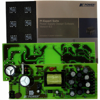
... TNY376PN. This power supply is intended as a general purpose evaluation platform for TinySwitch-PK The document contains the power supply specification, schematic, bill of materials, transformer documentation, printed circuit layout, and performance data. Figure 1 – Populated Circuit Board Photograph. Page Power Integrations Tel: +1 408 414 9200 Fax: +1 408 414 9201 www.powerint.com ...
Page 6
... Total Output Power Continuous Output Power Peak Output Power Efficiency Standby input power No load input power Environmental Conducted EMI Safety Surge Surge Ambient Temperature Power Integrations Tel: +1 408 414 9200 Fax: +1 408 414 9201 www.powerint.com Symbol Min Typ Max 85 265 50/60 ...
Page 7
... Schematic Page Figure 2 – Schematic. Tel: +1 408 414 9200 Fax: +1 408 414 9201 Power Integrations www.powerint.com ...
Page 8
... TinySwitch-PK family so low, since switching losses are the dominant loss mechanism at light loading. Additionally, since the amount of energy per switching cycle is fixed by Power Integrations Tel: +1 408 414 9200 Fax: +1 408 414 9201 www.powerint.com ) while it is turned on ...
Page 9
... This sets the peak current threshold to the minimum, typical, and maximum level. Refer to the data sheet for the specific current limit for each TinySwitch-PK device. Page The combined currents passing through R13 are Tel: +1 408 414 9200 Fax: +1 408 414 9201 LIMIT Power Integrations www.powerint.com ...
Page 10
... PCB Layout Power Integrations Tel: +1 408 414 9200 Fax: +1 408 414 9201 www.powerint.com Figure 3 – Printed Circuit Layout. Page ...
Page 11
... ECQU2A473ML Panasonic Nippon EKZE250ELL221MHB5D Chemi-Con Nippon EKMG500ELL100ME11D Chemi-Con 440LT33-R Vishay Nippon EKZE250ELL470ME11D Chemi-Con Nippon EKZE100ELL102MH20D Chemi-Con C317C104M5U5TA Kemet Nippon EKZE100ELL471MHB5D Chemi-Con Nippon EKZE250ELL101MF11D Chemi-Con FR106 Diodes Inc. 1N4007 Vishay UF4003-E3 Vishay Vishay 1N5819-E3 Vishay 37013150410 Wickman 26-50-3039 Molex Power Integrations www.powerint.com ...
Page 12
... VR1 A *A TNY375P can be used for U4, with a reduced power output. See Appendix A in this report. Note: Parts listed above are RoHS compliant. Power Integrations Tel: +1 408 414 9200 Fax: +1 408 414 9201 www.powerint.com 8 Position ( header, 0.156 pitch, Vertical Wire Jumper, insulated, 22 AWG, 0 ...
Page 13
... Pin 1 to Pin 4, all other windings open Measured at 132 kHz. Pin 1 to Pin 4, all other windings open Pin 1 to Pin 4, Pins 6-12 shorted Description Tel: +1 408 414 9200 Fax: +1 408 414 9201 +3.3 V 8,9, 3000 V ac 0.813 mH +/- 12% 300 kHz (Min.) 30 µH Max. 2 Power Integrations www.powerint.com ...
Page 14
... The following figure shows the copper foils to be used for +3.3 V and +5 V outputs (W4 and W5) #26 Copper Finish Pin 11 Wire 50mm +5 Vout 1T Copper Foil 12 0.52mm Thick. Power Integrations Tel: +1 408 414 9200 Fax: +1 408 414 9201 www.powerint.com Connection to a pin Figure 5 – Transformer Build Diagram. #26 Copper Connect Pin 7 Wire 77mm +3 ...
Page 15
... Finish on pin 8,9,10 using item [6] at the finish leads. 2 Layers of tape [11] for insulation. Outer Insulation Assemble and secure core halves. Item [1] Core Assembly Dip Varnish uniformly in item [12]. Final Assembly Page Power Integrations Tel: +1 408 414 9200 Fax: +1 408 414 9201 www.powerint.com ...
Page 16
... Design Spreadsheet ACDC_TinySwitch-PK_ 041207; Rev.0.22; Copyright INPUT Power Integrations 2007 ENTER APPLICATION VARIABLES VACMIN 85 VACMAX 265 5.00 Peak Load Current, IO 2.60 Peak Power Continuous / Average Power 7 3.00 CIN 44.00 ENTER TinySwitch-PK VARIABLES TinySwitch-PK TNY376 Chosen Device Chose Configuration INC ...
Page 17
... Secondary Wire Gauge (Rounded up to next larger standard AWG value) 678 Volts Maximum Drain Voltage Estimate (Assumes 20% zener clamp tolerance and an additional 10% temperature tolerance) 20 Volts Output Rectifier Maximum Peak Inverse Voltage Tel: +1 408 414 9200 Fax: +1 408 414 9201 Power Integrations www.powerint.com ...
Page 18
... For adapters that are single input voltage only, the measurement is made at the rated single nominal input voltage (115 VAC or 230 VAC); for universal input adapters the measurement is made at both nominal input voltages (115 VAC and 230 VAC). Power Integrations Tel: +1 408 414 9200 Fax: +1 408 414 9201 www.powerint.com ...
Page 19
... Full Load 115 VAC 230 VAC 25 83.9 78.2 50 78.2 73.5 75 75.0 74.2 100 73.8 73.1 Average 77.7 74.8 CEC specified minimum 68.1 average efficiency (%) 100 150 Vin (VAC) Tel: +1 408 414 9200 Fax: +1 408 414 9201 200 250 300 Power Integrations www.powerint.com ...
Page 20
... and 3 W. 2.5 1 Watt Input Power 2 2 Watts Input Power 3 Watts Input Power 1 Power Integrations Tel: +1 408 414 9200 Fax: +1 408 414 9201 www.powerint.com 100 150 Input Voltage (Volts) Figure 9 – Output Power vs. Line Voltage. 200 250 300 Page ...
Page 21
... OUTPUT POWER (WATTS) +5 VOLT REGULATION Vs PS OUTPUT POWER 5.26 5.3 5.1 5.07 5.06 5.07 5 5.04 4.83 4. OUTPUT POWER (WATTS) Tel: +1 408 414 9200 Fax: +1 408 414 9201 +3.3 V REGULATION UPPER LIMIT LOWER LIMIT 3. REGULATION UPPER LIMIT LOWER LIMIT 5. Power Integrations www.powerint.com ...
Page 22
... Figure 13 – -12 V Regulation vs. total output power. Power Integrations Tel: +1 408 414 9200 Fax: +1 408 414 9201 www.powerint.com +12 VOLT REGULATION 13.11 13.03 12.26 11 OUTPUT POWER (WATTS) -12 VOLT REGULATION -12 V CROSS REGULATION 13.44 13.34 12 ...
Page 23
... Figure 14 – Line Regulation, Room Temperature, Full Load. Page 12.78 12.26 5.06 3.28 100 150 200 Vin (VAC) Tel: +1 408 414 9200 Fax: +1 408 414 9201 13.09 13.1 12.54 12.52 5.19 5.19 3.24 3.24 250 300 Power Integrations www.powerint.com ...
Page 24
... Test chamber temperature was set to 50 °C. TNY376 (U4) 90 VAC, 7.5 W load, 21ºC Ambient Figure 15 – Infrared Thermograph of Open Frame Operation, at Room Temperature Power Integrations Tel: +1 408 414 9200 Fax: +1 408 414 9201 www.powerint.com Temperature (°C) Item ...
Page 25
... Lower 200 V / div. DRAIN Figure 19 – Start-up Profile, 230 VAC. Bottom Trace Output div. Next Trace: 3.3 V Output div. Next Trace: +12 V Output div. Top Trace: -12 V Output div div Power Integrations Tel: +1 408 414 9200 Fax: +1 408 414 9201 www.powerint.com ...
Page 26
... Bottom Trace Output div. Next Trace: 3.3 V Output div. Next Trace: +12 V Output at 0 div. Top Trace: -12 V Output at 0 div div Power Integrations Tel: +1 408 414 9200 Fax: +1 408 414 9201 www.powerint.com Figure 21 – 265 VAC Input and Maximum Load. Upper 0 div. ...
Page 27
... A-0.5 A-0.375 A Load Step. All other outputs are at full load. Bottom Trace Output div. Next Trace: 3.3 V Output div. Next Trace: +12 V Output at 0 div. Top Trace: -12 V Output at 0 div div Tel: +1 408 414 9200 Fax: +1 408 414 9201 . Power Integrations www.powerint.com ...
Page 28
... A-0.6 A-0.375 A Load Step. All other outputs are at full load Output div div Power Integrations Tel: +1 408 414 9200 Fax: +1 408 414 9201 www.powerint.com Figure 28 – Transient Response, 230 VAC, +3.3 V 0.375 A-0.6 A-0.375 A Load Step. All other outputs are at full load. ...
Page 29
... Figure 32 – Oscilloscope Probe with Probe Master 5125BA BNC Adapter. (Modified with wires for probe ground for ripple measurement, and two parallel decoupling capacitors added) Page Probe Ground Probe Tip Power Integrations Tel: +1 408 414 9200 Fax: +1 408 414 9201 www.powerint.com ...
Page 30
... Measurement Results Figure 33 – 3.3 V Ripple, 115 VAC, Full Load div. Figure 35 – +12V Ripple, 115 VAC, Full Load /div. Power Integrations Tel: +1 408 414 9200 Fax: +1 408 414 9201 www.powerint.com Figure 34 – Ripple, 115 VAC, Full Load div. ...
Page 31
... Unit passes under all test conditions. Page Input Injection Injection Location Phase (°) (VAC) 230 230 230 230 230 230 230 L 230 L Tel: +1 408 414 9200 Fax: +1 408 414 9201 Test Result (Pass/Fail) 90 Pass 90 Pass 90 Pass 90 Pass 90 Pass 90 Pass 90 Pass 90 Pass Power Integrations www.powerint.com ...
Page 32
... Figure 37 – Conducted EMI, Maximum Steady State Load, 115 VAC, 60 Hz, and EN55022 B Limits. Figure 38 – Conducted EMI, Maximum Steady State Load, 230 VAC, 60 Hz, and EN55022 B Limits. Power Integrations Tel: +1 408 414 9200 Fax: +1 408 414 9201 www.powerint.com Page ...
Page 33
... TNY376 reached when delivering 7.5 Watts in the environment described above. Peak Power Capability (calculated) Continuous Power Delivery (for 50 ºC device temperature rise) Page This was the TNY375PN TNY376PN 11 7.2 W 7.5 W Power Integrations Tel: +1 408 414 9200 Fax: +1 408 414 9201 www.powerint.com ...
Page 34
... Revision History Date Author 22-May-07 SGK Power Integrations Tel: +1 408 414 9200 Fax: +1 408 414 9201 www.powerint.com Revision Description & changes 1.0 Initial publication Reviewed Page ...
Page 35
... Page Notes Power Integrations Tel: +1 408 414 9200 Fax: +1 408 414 9201 www.powerint.com ...
Page 36
... For the latest updates, visit our website: www.powerint.com Power Integrations reserves the right to make changes to its products at any time to improve reliability or manufacturability. Power Integrations does not assume any liability arising from the use of any device or circuit described herein. POWER INTEGRATIONS MAKES NO WARRANTY HEREIN AND SPECIFICALLY DISCLAIMS ALL WARRANTIES INCLUDING, WITHOUT LIMITATION, THE IMPLIED WARRANTIES OF MERCHANTABILITY, FITNESS FOR A PARTICULAR PURPOSE, AND NON-INFRINGEMENT OF THIRD PARTY RIGHTS ...