DEMOTS4956J STMicroelectronics, DEMOTS4956J Datasheet - Page 38
DEMOTS4956J
Manufacturer Part Number
DEMOTS4956J
Description
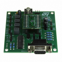
BOARD DEMO TS4956EIJT/EIKJT
Manufacturer
STMicroelectronics
Specifications of DEMOTS4956J
Amplifier Type
Class AB
Output Type
1-Channel (Mono) with Mono and Stereo Headphones
Max Output Power X Channels @ Load
1W x 1 @ 8 Ohm; 43mW x 2 @ 32 Ohm
Voltage - Supply
2.7 V ~ 5.5 V
Operating Temperature
-40°C ~ 85°C
Board Type
Fully Populated
Utilized Ic / Part
TS4956
Description/function
Audio Amplifiers
Operating Supply Voltage
2.7 V to 5.5 V
Product
Audio Modules
Lead Free Status / RoHS Status
Lead free / RoHS Compliant
For Use With/related Products
TS4956
Other names
497-6381
DEMOTS4956J
DEMOTS4956J
Available stocks
Company
Part Number
Manufacturer
Quantity
Price


TS4956
4
4.1
4.1.1
4.1.2
4.1.3
Application information
The TS4956 integrates four monolithic power amplifiers and has one differential input and
two single-ended inputs. The output amplifiers can be configured in 7 different modes as
one SE (single-ended) capacitively-coupled output, two phantom ground headphone
outputs and two BTL outputs.
configuration schemes and
modes.
This chapter gives information on how to configure the TS4956 in an application.
Output configurations
Shutdown
When the device is in shutdown mode, all of the device’s outputs are in a high impedance
state.
Single-ended output configuration (modes 5 and 6)
When the device is woken-up via the I²C interface, output amplifier on output MLO is biased
to the V
output is needed to block the V
V
capacitor C
between any given mode to mode 5 or 6.
When the device is in mode 5 or 6 where the single-ended output MLO is active, all other
outputs are in a high impedance state.
Phantom ground output configuration (modes 3 and 4)
In a phantom ground output configuration (modes 3 and 4) the internal buffer is connected
to the PHG pin and biased to the V
also biased to the V
one to the PHG buffer. Therefore, no output capacitors are needed. The advantage of the
PHG output configuration is that there are fewer external components compared to an SE
configuration. However, note that in this configuration, the device has a higher power
dissipation (see
All other inactive outputs are in the high impedance state except for the MLO output, which
is biased to V
To achieve better crosstalk results in this case, each speaker should be connected with a
separate PHG wire (two speakers connected with four wires) as shown in
page 5
speakers connected with three wires).
CC
/2 voltage is present on this output in all modes (modes 1 to 7) to keep the output
(instead of using only one common PHG wire for both speakers, that is, two
CC
/2 voltage. In this configuration an output capacitor, C
out
CC
charged and to improve pop performance on this output during the switching
/2 voltage.
Section 4.3: Power dissipation and efficiency on page
CC
/2 voltage. One end of the load is connected to output amplifier and
Table 7 on page 8
Figure 1 on page 5
CC
/2 voltage and couples the audio signal to the load.
CC
/2 voltage. Output amplifiers (pins LHP and RHP) are
describes these configurations in different
and
Figure 2 on page 6
out
Application information
, on the single-ended
40).
show these
Figure 1 on
38/55
Related parts for DEMOTS4956J
Image
Part Number
Description
Manufacturer
Datasheet
Request
R

Part Number:
Description:
Manufacturer:
STMicroelectronics
Datasheet:

Part Number:
Description:
DEMO BOARD FOR HMC6042/HMC1041Z
Manufacturer:
Honeywell Microelectronics & Precision Sensors

Part Number:
Description:
DEMO BOARD FOR HMC1042L/HMC1041Z
Manufacturer:
Honeywell Microelectronics & Precision Sensors
Datasheet:

Part Number:
Description:
KIT DEMO 4 SENSOR CHAN RS232
Manufacturer:
VTI Technologies
Datasheet:


Part Number:
Description:
DEMO: DC Power Supply, 32 Volts, 3 Amps
Manufacturer:
Tektronix
Part Number:
Description:
DEMO: Programmable DC Power Supply, 32 Volts, 3 Amps
Manufacturer:
Tektronix
Part Number:
Description:
STMicroelectronics [RIPPLE-CARRY BINARY COUNTER/DIVIDERS]
Manufacturer:
STMicroelectronics
Datasheet:
Part Number:
Description:
STMicroelectronics [LIQUID-CRYSTAL DISPLAY DRIVERS]
Manufacturer:
STMicroelectronics
Datasheet:

Part Number:
Description:
BOARD EVAL FOR MEMS SENSORS
Manufacturer:
STMicroelectronics
Datasheet:
Part Number:
Description:
NPN TRANSISTOR POWER MODULE
Manufacturer:
STMicroelectronics
Datasheet:
Part Number:
Description:
TURBOSWITCH ULTRA-FAST HIGH VOLTAGE DIODE
Manufacturer:
STMicroelectronics
Datasheet: