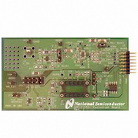
ADC121C02XEB/NOPB National Semiconductor, ADC121C02XEB/NOPB Datasheet - Page 6

ADC121C02XEB/NOPB
Manufacturer Part Number
ADC121C02XEB/NOPB
Description
BOARD EVAL FOR ADC121C-21
Manufacturer
National Semiconductor
Series
PowerWise®r
Specifications of ADC121C02XEB/NOPB
Number Of Adc's
1
Number Of Bits
12
Sampling Rate (per Second)
188.9k
Data Interface
Serial
Inputs Per Adc
1 Single Ended
Input Range
0 ~ 5.5 V
Power (typ) @ Conditions
3.67mw @ 188.9kSPS
Voltage Supply Source
Single Supply
Operating Temperature
-40°C ~ 105°C
Utilized Ic / Part
ADC121C021,ADC121C027
Silicon Manufacturer
National
Silicon Core Number
ADC121C021, ADC121C027
Kit Application Type
Data Converter
Application Sub Type
ADC
Kit Contents
Board
Lead Free Status / RoHS Status
Lead free / RoHS Compliant
Other names
ADC121C02XEB
4. Connect the J1 header on the ADC121C021
5. Perform step 6 of section 3.1 to drive the
6. Connect a clean (not switching) +5.0V power
6
evaluation board to the WV4 serial connector
(J7) on the WV4 board. Refer to Figure 6 for
the serial connection and Figure 7 for the J1
header pin out.
analog input. For information on changing the
configuration of the analog input section, read
Section 2.0 Board Assembly for details. The
board comes ready for a DC coupled input
signal.
source with a 350mA current limit to power
connector J1 on the WV4 board. Turn on the
power supply.
SDA
(ADC)
SDA
(ADC)
N/C
GND
N/C
SDA
(EEPROM)
+3.3V
Figure 6: WV4 to ADC121C02XEB Connection
Figure 7: J1 (WV4S) Header Pin Out
3
5
7
9
11
13
1
2
4
6
8
10
12
14
(EEPROM)
SCL
GND
+5V
7. Refer to Section 5.0 on Software Operation
4.0 Functional Description
4.1 Jumper Settings
Table 1 describes the function of the various
jumpers on the ADC121C021 evaluation board.
The evaluation board schematic is shown in
Figure 10.
Pins 9 & 10
Pins 1 & 2
Pins 3 & 4
Pins 5 & 6
Pins 7 & 8
Jumper
and Settings to setup the WaveVision 4
software.
JP1
JP2
JP3
JP5
JP6
JP7
Table 1: Jumper Configurations
Select 5.0V supply from WV4S connector.
Select 3.3V regulated supply from WV4S
Select direct V
[LM1117MPX-3.3 on the WV4 board]
Select 4.1V shunt reference supply.
Pins 1 & 2
Select external supply from TP7.
Enable 4.1V Shunt Reference
circuit
Enable I
Jumper JP5 (VA SELECT)
VA SELECT (See Below)
Permanently shorted
[LM4050-4.1]
[LM4050-4.1]
2
connector.
IN
C Pull-up resistors
Not Used
Not Used
http://www.national.com
Select Amplified V
circuit [LMP7731]
Pins 2 & 3
IN


