ADC121C02XEB/NOPB National Semiconductor, ADC121C02XEB/NOPB Datasheet - Page 3
ADC121C02XEB/NOPB
Manufacturer Part Number
ADC121C02XEB/NOPB
Description
BOARD EVAL FOR ADC121C-21
Manufacturer
National Semiconductor
Series
PowerWise®r
Specifications of ADC121C02XEB/NOPB
Number Of Adc's
1
Number Of Bits
12
Sampling Rate (per Second)
188.9k
Data Interface
Serial
Inputs Per Adc
1 Single Ended
Input Range
0 ~ 5.5 V
Power (typ) @ Conditions
3.67mw @ 188.9kSPS
Voltage Supply Source
Single Supply
Operating Temperature
-40°C ~ 105°C
Utilized Ic / Part
ADC121C021,ADC121C027
Silicon Manufacturer
National
Silicon Core Number
ADC121C021, ADC121C027
Kit Application Type
Data Converter
Application Sub Type
ADC
Kit Contents
Board
Lead Free Status / RoHS Status
Lead free / RoHS Compliant
Other names
ADC121C02XEB


J2: INPUT
[LMP7731]
SELECT
U2: AMP
JP5: VA
1.0 Introduction
This Design Kit (consisting of the ADC Evaluation
Board and this User's Guide) is designed to ease
evaluation
Semiconductor’s ADC121C021 family of Analog-
to-Digital Converters. The ADCs can operate at
speeds up to 188.9 kSPS. The converter features
an I
Guide supports all three resolutions and both
package options of the ADC121C021 ADC family.
All the devices in the family (ADC121C021,
ADC121C027,
ADC081C021, and ADC081C027) will be referred
to as the ADC121C021 in this document. The
ADCXX1C021 options offer an ALERT output pin,
whereas, the ADCXX1C027 offers an address
selection pin. The board comes stuffed with the
ALERT option (ADCXX1C021). To evaluate the
Address Option (ADCXX1C027) with this board,
please
samples. Use care when de-soldering the ADC to
ensure the pads of U3 are not damaged.
The evaluation board can be used in either of two
modes. In Stand Alone, suitable test equipment
such as a logic analyzer with a pattern generator
can be used with the board to evaluate the
ADC121C021’s performance.
3
REF Enable
2
JP7: 4.1V
C interface and an Alert function. This User’s
go
to
and
ADC101C021,
www.national.com
JP1: INPUT
design-in
SELECT
[LM4050-4.1]
U5: REF
ADC101C027,
of
and
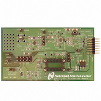
Figure 1: Component Locations
National
order
[ADC121C021]
U3: ADC
In the Computer mode, data capture and
evaluation are simplified by connecting the
evaluation board to National Semiconductor's
WaveVision 4 Data Capture Board (order number
WAVEVSN BRD 4.1 or higher) which connects to
a personal computer through a USB port and runs
WaveVision 4 software revision 4.4 or higher.
The latest version of the WaveVision 4 software
should
http://www.national.com/adc.
Note: WaveVision software version 4.4 or higher
is required to evaluate this part with the WV4
Evaluation System.
The WaveVision 4 software operates under
Microsoft Windows.
input is digitized, captured, and displayed on a PC
monitor in the time and frequency domains.
The software will perform an FFT on the captured
data upon command. This FFT plot shows the
dynamic performance in the form of SNR, SINAD,
THD, SFDR, and ENOB. A software histogram of
the captured data is also available. WaveVision
also provides control of the ADC’s internal
registers through the WaveVision4 software.
The signal at analog input J2 is digitized by U3,
the ADC121C021.
be
downloaded
The signal at the analog
from
JP2: I
http://www.national.com
2
Enable
C PULL-UP
the
Connector
J1: WV4S
web
at
Related parts for ADC121C02XEB/NOPB
Image
Part Number
Description
Manufacturer
Datasheet
Request
R

Part Number:
Description:
National Semiconductor [8-Bit D/A Converter]
Manufacturer:
National Semiconductor
Datasheet:
Part Number:
Description:
National Semiconductor [Media Coprocessor]
Manufacturer:
National Semiconductor
Datasheet:
Part Number:
Description:
Digitally Controlled Tone and Volume Circuit with Stereo Audio Power Amplifier, Microphone Preamp Stage and National 3D Sound
Manufacturer:
National Semiconductor
Datasheet:
Part Number:
Description:
Digitally Controlled Tone and Volume Circuit with Stereo Audio Power Amplifier, Microphone Preamp Stage and National 3D Sound
Manufacturer:
National Semiconductor
Datasheet:
Part Number:
Description:
AC97 Rev 2 Codec with Sample Rate Conversion and National 3D Sound
Manufacturer:
National Semiconductor
Part Number:
Description:
Manufacturer:
National Semiconductor
Datasheet:
Part Number:
Description:
Manufacturer:
National Semiconductor
Datasheet:
Part Number:
Description:
General Purpose, Low Voltage, Low Power, Rail-to-Rail Output Operational Amplifiers
Manufacturer:
National Semiconductor
Datasheet:
Part Number:
Description:
8-bit 20 MSPS flash A/D converter.
Manufacturer:
National Semiconductor
Datasheet:
Part Number:
Description:
Low Noise Quad Operational Amplifier
Manufacturer:
National Semiconductor
Datasheet:
Part Number:
Description:
Quad Differential Line Receivers
Manufacturer:
National Semiconductor
Datasheet:
Part Number:
Description:
Quad High Speed Trapezoidal? Bus Transceiver
Manufacturer:
National Semiconductor
Datasheet:
Part Number:
Description:
Dual Line Receiver
Manufacturer:
National Semiconductor
Datasheet:
Part Number:
Description:
TTL to 10k ECL Level Translator with Latch
Manufacturer:
National Semiconductor
Datasheet: