ADC121C02XEB/NOPB National Semiconductor, ADC121C02XEB/NOPB Datasheet
ADC121C02XEB/NOPB
Specifications of ADC121C02XEB/NOPB


Related parts for ADC121C02XEB/NOPB

ADC121C02XEB/NOPB Summary of contents
Page 1
... National Semiconductor Evaluation Board User's Guide 2 I C-Compatible, 12-Bit, 10-Bit, or 8-Bit Analog-to-Digital Converter (ADC) with Alert Function ADC121C021 ALERT Option ADC121C027 ADDRESS Option NOTE: The Evaluation Board is shipped with the Alert Option of the ADC. To evaluate the Address Option, please order samples from www.national.com. ...
Page 2
Introduction ............................................................................................................................3 2.0 Board Assembly .....................................................................................................................4 3.0 Quick Start .............................................................................................................................5 3.1 Stand Alone Mode.....................................................................................................5 3.2 Computer Mode ........................................................................................................5 4.0 Functional Description............................................................................................................6 4.1 Jumper Settings ........................................................................................................6 4.2 Analog Input Signal ...................................................................................................7 4.3 ADC Reference Circuitry........................................................................................... Interface ...
Page 3
... JP7: 4.1V REF Enable [LM4050-4. the Computer mode, data capture and evaluation are simplified by connecting the evaluation board to National Semiconductor's WaveVision 4 Data Capture Board (order number of National WAVEVSN BRD 4.1 or higher) which connects to a personal computer through a USB port and runs WaveVision 4 software revision 4 ...
Page 4
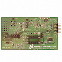
Board Assembly The ADC121C02XEB evaluation board comes fully assembled and ready for use. The provided jumpers are in their recommended locations and suit the needs of most users. Refer to the Bill of Materials for a description of components, ...
Page 5
The LM4050-4.1 Precision, Micropower, Shunt Voltage Reference is included ADC121C02XEB as a clean reference solution for the ADC. To evaluate the ADC using the LM4050, simply short pins 1 & JP7, and move the VA_SELECT jumper to pins ...
Page 6
Connect the J1 header on the ADC121C021 evaluation board to the WV4 serial connector (J7) on the WV4 board. Refer to Figure 6 for the serial connection and Figure 7 for the J1 header pin out. Figure 6: WV4 ...
Page 7
Analog Input Signal There are three basic options for connecting an input signal to the ADC. The three options facilitate AC-coupled and DC-coupled signals. The first way to apply an input signal to the ADC is to connect it ...
Page 8
Automatic Conversion Mode The Automatic Conversion Mode configures the ADC to continually perform conversions without receiving “read” instructions controller activated by writing a non-zero value into the Cycle Time bits “D[7:5]” of the Configuration Register. Various conversion ...
Page 9
Apply power as specified in Section 4.4, click on the "Reset" button and await the firmware to download. 4. Click on the "Close" button to close the System Settings window. 5. Navigate to the ADC121C021 Eval Board Window. This ...
Page 10
To view an FFT of the data captured, click on the ‘FFT’ tab. This plot may be zoomed in on the data plot. A display of dynamic parameters in the form of SINAD, SNR, THD, SFDR and ENOB will be ...
Page 11
Troubleshooting WaveVision 5.4.1 Problems Problem 1: The “ADC121C021 Eval Board” Control Panel appears briefly, but disappears after powering on the WaveVision board. Try Solutions A, B, and C. After trying these solutions, the WaveVision system must be hard reset ...
Page 12
Evaluation Board Specifications Board Size: 3.1" x 1.85" (7 4.6 cm) Power Requirements: Min: +2.7V, 10mA I2C Interface Speed: 100 kHz, 400kHz, or 3.4 MHz Analog Input Range: GND 7.0 Test Points, Connectors, and ...
Page 13
Hardware Schematic Figure 10: ADC121C021 Evaluation Board Schematic 13 SDA GND 5 4 SCL VCC ...
Page 14
Evaluation Board Layers Figure 11: ADC121C021 Evaluation Board: All Layers with Silk Screen Figure 12: ADC121C021 Evaluation Board: Top Layer Figure 13: ADC121C021 Evaluation Board: Bottom Layer 14 http://www.national.com ...
Page 15
Evaluation Board Bill of Materials Qty Reference Value Ohm 470pF 2 C3,C7 10.0uF 5 C4,C5, 0.1uF C8,C12 1 C6,C11 1.0uF 1 C10 0 Ohm R 1 JP1 INPUT SELECT 1 ...
Page 16
... European EMC Directive 89/336/EEC, or for compliance with any other electromagnetic compatibility requirements. National Semiconductor Corporation does not assume any responsibility for use of any circuitry or software supplied or described. No circuit patent licenses are implied. ...