CDB5532U Cirrus Logic Inc, CDB5532U Datasheet - Page 27
CDB5532U
Manufacturer Part Number
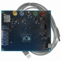
CDB5532U
Description
BOARD EVAL FOR CS5532U ADC
Manufacturer
Cirrus Logic Inc
Specifications of CDB5532U
Number Of Adc's
2
Number Of Bits
24
Sampling Rate (per Second)
3.84k
Data Interface
Serial
Inputs Per Adc
1 Differential
Input Range
±2.5 V
Power (typ) @ Conditions
35mW @ 3.84kSPS
Voltage Supply Source
Analog and Digital, Dual ±
Operating Temperature
-40°C ~ 85°C
Utilized Ic / Part
CS5532
Description/function
Audio DSPs
Operating Supply Voltage
5 V
Product
Audio Modules
For Use With/related Products
C8051F320
Lead Free Status / RoHS Status
Contains lead / RoHS non-compliant
Lead Free Status / RoHS Status
Lead free / RoHS Compliant, Contains lead / RoHS non-compliant
Other names
598-1159


2.4. Setting up the CSRs for a Measurement
The CS5532/34 have four Channel-Setup Registers
(CSRs). Each CSR contains two 16-bit Setups which
are programmed by the user to contain data conver-
sion information such as: 1) which physical channel
will be converted, 2) at what gain will the channel be
converted, 3) at what word rate will the channel be
converted, 4) will the output conversion be unipolar
or bipolar, 5) what will be the state of the output
latch during the conversion, 6) will the converter de-
lay the start of a conversion to allow time for the out-
put latch to settle before the conversion is begun, and
7) will the open circuit detect current source be acti-
vated for that Setup. In addition, when the OGS bit
in the Configuration Register is set, the Setup selects
which set of offset and gain registers to use when
performing conversions or calibrations. Note that a
particular physical input channel can be represent-
DS755F3
Filter Rate Select, FRS[19]
NU (Not Used)[18:0]
0
1
0
Use the default output word rates.
Scale all output word rates and their corresponding filter characteristics by a factor of 5/6.
Must always be logic 0. Reserved for future upgrades.
ed in more than one Setup with different output
rates, gain ranges, etc. (i.e. each Setup is indepen-
dently defined). Refer to section 2.4.1 for more de-
tails about the Channel Setup Registers.
Each 32-bit CSR is individually accessible and
contains two 16-bit Setups. As an example, to con-
figure Setup 1 in the CS5532/34 with the write in-
dividual channel-setup register command (0x05
hexadecimal), bits 31 to 16 of CSR 1 contains the
information for Setup 1 and bits 15 to 0 contain the
information for Setup 2. Note that while read-
ing/writing CSRs, two Setups are accessed in pairs
as a single 32-bit CSR register. Even if one of the
Setups isn’t used, it must be written to or read. Ex-
amples detailing the power of the CSRs are provid-
ed in section 2.6.3.
CS5532/34-BS
27
Related parts for CDB5532U
Image
Part Number
Description
Manufacturer
Datasheet
Request
R

Part Number:
Description:
Development Kit
Manufacturer:
Cirrus Logic Inc
Datasheet:
Part Number:
Description:
Development Kit
Manufacturer:
Cirrus Logic Inc
Datasheet:


Part Number:
Description:
High-efficiency PFC + Fluorescent Lamp Driver Reference Design
Manufacturer:
Cirrus Logic Inc
Datasheet:
Part Number:
Description:
Development Kit
Manufacturer:
Cirrus Logic Inc
Datasheet:
Part Number:
Description:
Development Kit
Manufacturer:
Cirrus Logic Inc
Datasheet:

Part Number:
Description:
Development Kit
Manufacturer:
Cirrus Logic Inc
Datasheet:
Part Number:
Description:
Development Kit
Manufacturer:
Cirrus Logic Inc
Datasheet:
Part Number:
Description:
Development Kit
Manufacturer:
Cirrus Logic Inc
Datasheet:
Part Number:
Description:
Development Kit
Manufacturer:
Cirrus Logic Inc
Datasheet:

Part Number:
Description:
EVALUATION BOARD FOR CS8427
Manufacturer:
Cirrus Logic Inc
Datasheet:

Part Number:
Description:
BOARD EVAL FOR CS8416 RCVR
Manufacturer:
Cirrus Logic Inc
Datasheet:

Part Number:
Description:
EVALUATION BOARD FOR CS8420
Manufacturer:
Cirrus Logic Inc
Datasheet:

Part Number:
Description:
KIT DEVELOPMENT EP9315 ARM9
Manufacturer:
Cirrus Logic Inc
Datasheet:

Part Number:
Description:
KIT DEVELOPMENT EP9302 ARM9
Manufacturer:
Cirrus Logic Inc
Datasheet: