EVAL-AD7731EBZ Analog Devices Inc, EVAL-AD7731EBZ Datasheet

BOARD EVALUATION FOR AD7731

EVAL-AD7731EBZ

Manufacturer Part Number
EVAL-AD7731EBZ
Description
BOARD EVALUATION FOR AD7731
Manufacturer
Analog Devices Inc

Specifications of EVAL-AD7731EBZ

Number Of Adc's
1
Number Of Bits
24
Sampling Rate (per Second)
6.4k
Data Interface
Serial
Inputs Per Adc
3 Differential
Input Range
±1.28 V
Power (typ) @ Conditions
67.5mW @ 6.4kSPS
Voltage Supply Source
Analog and Digital
Operating Temperature
-40°C ~ 85°C
Utilized Ic / Part
AD7731
Lead Free Status / RoHS Status
Lead free / RoHS Compliant
a
INTRODUCTION
This Technical Note describes the evaluation board for the
AD7731, Process Control ADC. The AD7731 is a complete
analog front-end for process control applications. The device
has a proprietary programmable gain front end which allows
it to accept a range of input signal ranges including low-level
signals directly from a transducer. The part features three
buffered differential programmable gain analog inputs (which
can be configured as five pseudo-differential inputs) as well
as a differential reference input. Full data on the AD7731 is
available in the AD7731 data sheet available from Analog
Devices and should be consulted in conjunction with this
Technical Note when using the Evaluation Board.
Included on the evaluation board, along with the AD7731,
are an AD780, a +2.5 V ultra high precision bandgap
reference, a 4.9152MHz crystal and digital buffers to buffer
signals to and from the edge connectors.
REV. 0
Information furnished by Analog Devices is believed to be accurate and
reliable. However, no responsibility is assumed by Analog Devices for its
use, nor for any infringements of patents or other rights of third parties
which may result from its use. No license is granted by implication or
otherwise under any patent or patent rights of Analog Devices.
FEATURES
Operates from a Single +5V Supply
On-Board Reference and Digital Buffers
Various Linking Options
Direct Hook-Up to Printer Port of PC
PC Software for Control and Data Analysis
AIN4/D0
AIN3/D1
AV DD
AIN1
AIN2
AIN5
AIN6
AGND
DV DD
REFERENCE
AD780
FUNCTIONAL BLOCK DIAGRAM
DGND
REF IN
AD7731
ADC
One Technology Way, P.O. Box 9106, Norwood. MA 02062-9106, U.S.A.
Tel: 617/329-4700
Interfacing to this board is provided either through a 36-Way
Centronics Connector or through a 9-way D-type connector.
External sockets are provided for the analog inputs, an
external reference input option and an external master clock
option.
OPERATING THE AD7731 EVALUATION BOARD
Power Supplies
The evaluation board has four power supply input pins:
AV
with an AV
to the board must be +5V. This AV
power the AD780 reference. To run the board from a single
+5V supply, simply connect the AV
together.
Both AGND and DGND inputs are provided on the board.
AGND connects to the AD7731 AGND pin and also con-
nects to the GND pin of the AD780. DGND connects to the
DGND pin of the AD7731 and to the GND of the digital
chips on the board. The AGND and DGND planes are
connected at the AD7731. Therefore, it is recommended not
to connect AGND and DGND elsewhere in the system to
avoid ground loop problems. When using a single supply for
both AV
made to the board. This connection should be made to the
board's AGND input terminal.
Both supplies are decoupled to their respective ground plane
with 10µF tantalum and 0.1µF ceramic disc capacitors.
AV DD
MCLK IN
DD
, AGND, DV
9-WAY D-TYPE CONNECTOR
DD
BUFFERS
DD
and DV
of +5V. Therefore, the AV
DD
DD
, only one ground connection should be
Process Control ADC
and DGND. The AD7731 is specified
Evaluation Board for
CENTRONICS
CONNECTOR
EVAL-AD7731EB
36-WAY
DD
DD
voltage is also used to
DD
and DV
Fax: 617/326-8703
voltage supplied
DD
inputs

Related parts for EVAL-AD7731EBZ

EVAL-AD7731EBZ Summary of contents

Page 1

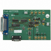
... AD7731 data sheet available from Analog Devices and should be consulted in conjunction with this Technical Note when using the Evaluation Board. Included on the evaluation board, along with the AD7731, are an AD780, a +2.5 V ultra high precision bandgap reference, a 4.9152MHz crystal and digital buffers to buffer signals to and from the edge connectors ...

Page 2

... EVAL-AD7731EB LINK OPTIONS There are a number of link options on the evaluation board which should be set for the required operating setup before using the board. The functions of these link options are described in detail below. Link No. Function LK1 This option selects the master clock option for the AD7731. The master clock source comes from the on- board crystal or from an external clock source via SKT11 ...

Page 3

... The evaluation board should be powered up before a cable is connected to either of the connectors. SKT2 is used to connect the evaluation board to the printer port (parallel port PC. Connection between the two is direct via a standard parallel printer port cable. SKT1 is used to connect the evaluation board to any other system. REV. A EVAL-AD7731EB 1 2 ...

Page 4

... Connect. These pins are not connected on the evaluation board. 19- Ground reference point for digital circuitry. Connects to the DGND plane on the evaluation board. 31- Connect. These pins are not connected on the evaluation board. Figure 3. SKT2 Pin Configuration is low, the nodes of the digital filter, the filter control logic, and the calibration line will return high prior to the next output update, remain high while the update is – ...

Page 5

... REV. A EVAL-AD7731EB RUNNING THE AD7731 INTERFACE SOFTWARE Included in the evaluation board package is a PC-compatible disk which contains software for controlling and evaluating the performance of the AD7731 using the printer port of a PC. There are a total of thirteen files on the distribution disk. To use the software, the user must have an IBM-compatible PC and Windows 3 ...

Page 6

... AD7731 software. Select Printer Port This button allows the user to select the printer port to which the AD7731 evaluation is connected. About This provides details of the software revision. Figure 4. Main Screen –6– ...

Page 7

... REV. A Figure 5. Program Screen Figure 6. Mode Register Screen –7– EVAL-AD7731EB ...

Page 8

... EVAL-AD7731EB –8– REV. A ...

Page 9

... C16 C17 Philips Mftrs No. 683 34339 Location Vendor R10 R11 ---------- R5 Bourns Bourns R9 Bourns Location Vendor Lk1 (4x2 way) Harwin Lk2, Lk3,Lk4 (2x2 way) Mftrs No. M20-9993606 Lk5 (3x2 way) Lk6,Lk7,Lk8,Lk9,Lk10,Lk11 (1x2 way) Pin Headers (12 required) Harwin Mftrs No. M7571-05 –9– EVAL-AD7731EB ±5% 0.25W ...

Page 10

... EVAL-AD7731EB SWITCH Component Sealed Push Button Switch SOCKETS Component Miniature BNC Connectors 9-Way D-Type Connector 36 Way Centronics Connector 2 Way Terminal Block Low profile socket CRYSTAL OSCILLATOR Component Identification 4.9152 MHz Oscillator Location Vendor Omron Mftrs No. B3W1000 Location Vendor SKT3 - SKT11 M/A - Com Greenpar Mftrs No ...

Page 11

... REV. A Figure 8. Component Placement Diagram. –11– EVAL-AD7731EB ...

Related keywords