CDB5560 Cirrus Logic Inc, CDB5560 Datasheet - Page 2
CDB5560
Manufacturer Part Number
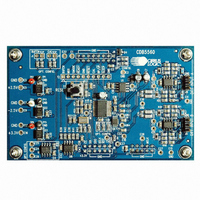
CDB5560
Description
DEV BOARD FOR CS5560 W/MUX
Manufacturer
Cirrus Logic Inc
Type
A/Dr
Specifications of CDB5560
Number Of Adc's
1
Number Of Bits
24
Sampling Rate (per Second)
50k
Data Interface
Serial
Inputs Per Adc
1 Differential
Input Range
±3 V
Power (typ) @ Conditions
90mW @ 2.5 V
Voltage Supply Source
Dual ±
Operating Temperature
-40°C ~ 85°C
Utilized Ic / Part
CS5560
Product
Data Conversion Development Tools
Conversion Rate
50 KSPS
Resolution
24 bit
Maximum Clock Frequency
16 MHz
Interface Type
SPI
Supply Voltage (max)
3.3 V
Supply Voltage (min)
- 2.5 V
For Use With/related Products
CS5560
Lead Free Status / RoHS Status
Contains lead / RoHS non-compliant
Lead Free Status / RoHS Status
Lead free / RoHS Compliant, Contains lead / RoHS non-compliant
Other names
598-1273
CDB5560-1
CDB5560-1


2
1. INTRODUCTION ....................................................................................................................... 3
2. QUICK START .......................................................................................................................... 5
3. HARDWARE DESCRIPTION ................................................................................................... 6
APPENDIX A. MAXIMIZING THE PERFORMANCE OF THE CS5560 ........................................ 9
APPENDIX B. BILL OF MATERIALS ........................................................................................ 10
APPENDIX C. SCHEMATICS ..................................................................................................... 11
APPENDIX D. LAYER PLOTS ................................................................................................... 16
APPENDIX E. CALIBRATION FUNCTION ................................................................................. 25
APPENDIX E. REVISION HISTORY .......................................................................................... 26
Figure 1. CDB5560 Block Diagram ................................................................................................. 4
Figure 2. CDB5560 Board Layout ................................................................................................... 5
Figure 3. Schematic - Block Diagram............................................................................................ 11
Figure 4. Schematic - Power Supplies .......................................................................................... 12
Figure 5. Schematic - Input Buffers and Multiplexer ..................................................................... 13
Figure 6. Schematic - CS5560 ...................................................................................................... 14
Figure 7. Schematic - Configuration & Misc. ................................................................................. 15
Figure 8. Top Silkscreen ............................................................................................................... 16
Figure 9. Top Solder Mask ............................................................................................................ 17
Figure 10. Top Routing.................................................................................................................. 18
Figure 11. Ground Plane ............................................................................................................... 19
Figure 12. Power Plane................................................................................................................. 20
Figure 13. Bottom Solder Mask..................................................................................................... 21
Figure 14. Bottom Silkscreen ........................................................................................................ 22
Figure 15. Top Solder Paste Mask................................................................................................ 23
Figure 16. Bottom Routing ............................................................................................................ 24
Table 1. Power Supply Connections ............................................................................................... 6
Table 2. Analog Input Connections ................................................................................................. 6
Table 3. Analog Input Channel Selection ........................................................................................ 7
Table 4. Hardware Configuration Signals........................................................................................ 8
Table 5. Serial Interface Connections ............................................................................................. 8
1.1 Overview ............................................................................................................................ 4
3.1 Absolute Maximum Ratings ............................................................................................... 6
3.2 Power Supply ..................................................................................................................... 6
3.3 Analog Section ................................................................................................................... 6
3.4 Digital Section .................................................................................................................... 8
A.1 PCB Layout Considerations .............................................................................................. 9
A.2 Hardware Considerations .................................................................................................. 9
3.3.1 Analog Input Buffers .............................................................................................. 6
3.3.2 Multiplexer ............................................................................................................. 7
3.3.3 ADC Reset ............................................................................................................ 7
3.3.4 Voltage Reference ................................................................................................ 7
3.3.5 ADC Reference Frequency ................................................................................... 7
3.4.1 Hardware Configuration ........................................................................................ 8
3.4.2 SPI™ Serial Port Communications ....................................................................... 8
TABLE OF CONTENTS
LIST OF FIGURES
LIST OF TABLES
CDB5560
DS713DB4
Related parts for CDB5560
Image
Part Number
Description
Manufacturer
Datasheet
Request
R

Part Number:
Description:
Development Kit
Manufacturer:
Cirrus Logic Inc
Datasheet:
Part Number:
Description:
Development Kit
Manufacturer:
Cirrus Logic Inc
Datasheet:


Part Number:
Description:
High-efficiency PFC + Fluorescent Lamp Driver Reference Design
Manufacturer:
Cirrus Logic Inc
Datasheet:
Part Number:
Description:
Development Kit
Manufacturer:
Cirrus Logic Inc
Datasheet:
Part Number:
Description:
Development Kit
Manufacturer:
Cirrus Logic Inc
Datasheet:

Part Number:
Description:
Development Kit
Manufacturer:
Cirrus Logic Inc
Datasheet:
Part Number:
Description:
Development Kit
Manufacturer:
Cirrus Logic Inc
Datasheet:
Part Number:
Description:
Development Kit
Manufacturer:
Cirrus Logic Inc
Datasheet:
Part Number:
Description:
Development Kit
Manufacturer:
Cirrus Logic Inc
Datasheet:

Part Number:
Description:
EVALUATION BOARD FOR CS8427
Manufacturer:
Cirrus Logic Inc
Datasheet:

Part Number:
Description:
BOARD EVAL FOR CS8416 RCVR
Manufacturer:
Cirrus Logic Inc
Datasheet:

Part Number:
Description:
EVALUATION BOARD FOR CS8420
Manufacturer:
Cirrus Logic Inc
Datasheet:

Part Number:
Description:
KIT DEVELOPMENT EP9315 ARM9
Manufacturer:
Cirrus Logic Inc
Datasheet:

Part Number:
Description:
KIT DEVELOPMENT EP9302 ARM9
Manufacturer:
Cirrus Logic Inc
Datasheet: