LMK03200EVAL National Semiconductor, LMK03200EVAL Datasheet - Page 12
LMK03200EVAL
Manufacturer Part Number
LMK03200EVAL
Description
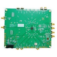
BOARD EVALUATION LMK03200
Manufacturer
National Semiconductor
Specifications of LMK03200EVAL
Main Purpose
Timing, Clock Conditioner
Embedded
No
Utilized Ic / Part
LMK03200
Primary Attributes
3 LVDS & 5 LVPECL Outputs, Integrated PLL & VCO
Secondary Attributes
3.15 V ~ 3.45 V Supply
Silicon Manufacturer
National
Silicon Core Number
LMK03200
Kit Application Type
Clock & Timing
Application Sub Type
Precision Clock Conditioner
Kit Contents
Board, Cable
Lead Free Status / RoHS Status
Lead free / RoHS Compliant


L M K 0 3 2 0 0
E V A L U A T I O N
B O A R D
O P E R A T I N G
I N S T R U C T I O N S
Recommended Equipment
Power Supply
The Power Supply should be a low noise power supply.
Phase Noise / Spectrum Analyzer
For measuring phase noise an Agilent E5052A is recommended. An Agilent E4445A PSA Spectrum
Analyzer with the Phase Noise option is also usable although the architecture of the E5052A is superior
for phase noise measurements. At frequencies less than 100 MHz the local oscillator noise of the PSA
is too high and measurements will be of the local oscillator, not the device under test.
Oscilloscope
For measuring delay an Agilent Infiniium DSO81204A was used.
Reference Oscillator
The on board crystal oscillator will provide a low noise reference signal to the device at offsets greater
than 1 kHz.
Note: The default loop filter has a loop bandwidth of ~60 kHz. Inside the loop bandwidth of a PLL the
noise is greatly affected by any noise on the reference oscillator (OSCin). Therefore any noise on the
oscillator less than 60 kHz will be passed through and seen on the outputs. For this reason the main
output of a Signal Generator is not recommended for driving OSCin in this setup.
12
Related parts for LMK03200EVAL
Image
Part Number
Description
Manufacturer
Datasheet
Request
R

Part Number:
Description:
Precision 0-delay Clock Conditioner With Integrated Vco
Manufacturer:
National Semiconductor Corporation
Datasheet:

Part Number:
Description:
National Semiconductor [8-Bit D/A Converter]
Manufacturer:
National Semiconductor
Datasheet:
Part Number:
Description:
National Semiconductor [Media Coprocessor]
Manufacturer:
National Semiconductor
Datasheet:
Part Number:
Description:
Digitally Controlled Tone and Volume Circuit with Stereo Audio Power Amplifier, Microphone Preamp Stage and National 3D Sound
Manufacturer:
National Semiconductor
Datasheet:
Part Number:
Description:
Digitally Controlled Tone and Volume Circuit with Stereo Audio Power Amplifier, Microphone Preamp Stage and National 3D Sound
Manufacturer:
National Semiconductor
Datasheet:
Part Number:
Description:
AC97 Rev 2 Codec with Sample Rate Conversion and National 3D Sound
Manufacturer:
National Semiconductor
Part Number:
Description:
Manufacturer:
National Semiconductor
Datasheet:
Part Number:
Description:
Manufacturer:
National Semiconductor
Datasheet:
Part Number:
Description:
General Purpose, Low Voltage, Low Power, Rail-to-Rail Output Operational Amplifiers
Manufacturer:
National Semiconductor
Datasheet:
Part Number:
Description:
8-bit 20 MSPS flash A/D converter.
Manufacturer:
National Semiconductor
Datasheet:
Part Number:
Description:
Low Noise Quad Operational Amplifier
Manufacturer:
National Semiconductor
Datasheet:
Part Number:
Description:
Quad Differential Line Receivers
Manufacturer:
National Semiconductor
Datasheet:
Part Number:
Description:
Quad High Speed Trapezoidal? Bus Transceiver
Manufacturer:
National Semiconductor
Datasheet:
Part Number:
Description:
Dual Line Receiver
Manufacturer:
National Semiconductor
Datasheet: