STEVAL-IHM020V1 STMicroelectronics, STEVAL-IHM020V1 Datasheet - Page 10
STEVAL-IHM020V1
Manufacturer Part Number
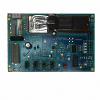
STEVAL-IHM020V1
Description
BOARD DEMO STCC08 AC SW DETECTOR
Manufacturer
STMicroelectronics
Type
Motor / Motion Controllers & Driversr
Specifications of STEVAL-IHM020V1
Main Purpose
Power Management, Triac Controller
Embedded
Yes, MCU, 8-Bit
Utilized Ic / Part
STCC08, ST7FLITE39F2
Primary Attributes
AC Switch Driver with Failure Mode Detector
Secondary Attributes
4 Toggle Switches for Failure Simulation, Capacitive Power Supply
Input Voltage
5 V
Product
Power Management Modules
Silicon Manufacturer
ST Micro
Silicon Core Number
STCC08
Kit Application Type
Power Management
Application Sub Type
AC Switch Failure Mode Detector
Kit Contents
Board Docs
Lead Free Status / RoHS Status
Lead free / RoHS Compliant
For Use With/related Products
ST7LITE39F2
Other names
497-8403
Available stocks
Company
Part Number
Manufacturer
Quantity
Price


Features
3
3.1
Note:
3.2
Table 3.
10/23
MCU
LEDs (two LEDs maximum
can be ON at the same time)
Maximum current consumed
by STCC08 (include the gate
current of the ACS)
Others (mechanical switch)
Total
Device
Features
ST7LITE39F2 microcontroller
The 8-bit MCU used in this board is the ST7LITE39F2. It belongs to the ST7 family of
microcontrollers, and offers a large number of features at minimum cost.
●
●
The MCU firmware has been developed only to evaluate the STCC08 device and is not
compliant with the class B (IEC60335-1 Ed4) requirements.
DC capacitive power supply
A DC capacitive power supply is used on the board. One peculiarity of this DC power supply
is that it is “negative”. The V
voltage is 5 V below neutral. Such a connection is mandatory to drive the ACS. Indeed, the
ACS can only be triggered by a negative current (i.e. sourced from the gate). The maximum
average current absorbed by the board is about 44 mA (see
C16 capacitor value has been used to ensure that the board works correctly in the worst
application conditions (230 V/110 V
Maximum average current sunk by the board
Note that a 43.2 Ω R
temperature must be 0 °C in order to work correctly the board. For lower ambient
The peripheral hardware requirements are reduced to a minimum:
–
–
In the MCU firmware, four options must be set:
–
–
–
–
No quartz or external resonator is used. Instead, an internal RC-oscillator in the
ST7LITE3 is used to generate the clock
No external RESET circuit is used
Software watchdog activation
RC oscillator selection
PLL disabled
Low voltage detection selection
2.5 mA
15 mA
26 mA
0.5 mA
44 mA
consumption
Average
current
IG
resistor (R23) value is used. In this case, the minimum ambient
CC
LED STCC08 controlled
LEDs visualizing the ACS failure
R
V
R
Maximum supply current in run mode. F
V
terminal is connected to neutral. This means that the GND
CC_MAX
CC_Max
19
IG
=R
= 43.2 ± 1% (R23)
RMS
20
= R
=5.5 V
=5.5 V, temperature = 0° C
line voltage ± 10% and V
21
= R
22
=475 Ω ± 1%
Comments
Table
CC
CPU
3). In this case, a 2.2 µF
± 10%).
=1 MHz and V
CC
UM0583
=5.5 V
Related parts for STEVAL-IHM020V1
Image
Part Number
Description
Manufacturer
Datasheet
Request
R

Part Number:
Description:
BOARD EVAL FOR MEMS SENSORS
Manufacturer:
STMicroelectronics
Datasheet:

Part Number:
Description:
KIT DEV STARTER ST10F276Z5
Manufacturer:
STMicroelectronics
Datasheet:

Part Number:
Description:
BOARD EVAL HDMI $ VIDEO SWITCH
Manufacturer:
STMicroelectronics
Datasheet:

Part Number:
Description:
BOARD DEMO ACCELEROMETER DIL24
Manufacturer:
STMicroelectronics
Datasheet:

Part Number:
Description:
BOARD STLM75/STDS75/ST72F651
Manufacturer:
STMicroelectronics
Datasheet:

Part Number:
Description:
EVAL BOARD 3AXIS MEMS ACCELLRMTR
Manufacturer:
STMicroelectronics
Datasheet:

Part Number:
Description:
BOARD EVAL 8BIT MICRO + TDE1708
Manufacturer:
STMicroelectronics
Datasheet:

Part Number:
Description:
EVAL BOARD A/D TS4657
Manufacturer:
STMicroelectronics
Datasheet:

Part Number:
Description:
BOARD ADAPTER 20DIP LIS3LV02DL
Manufacturer:
STMicroelectronics
Datasheet:

Part Number:
Description:
BOARD DEMO STM8S207R6/LIS331DLH
Manufacturer:
STMicroelectronics
Datasheet:

Part Number:
Description:
STMicroelectronics [RIPPLE-CARRY BINARY COUNTER/DIVIDERS]
Manufacturer:
STMicroelectronics
Datasheet:
Part Number:
Description:
STMicroelectronics [LIQUID-CRYSTAL DISPLAY DRIVERS]
Manufacturer:
STMicroelectronics
Datasheet:
Part Number:
Description:
BOARD EVAL FOR MEMS SENSORS
Manufacturer:
STMicroelectronics
Datasheet: