STEVAL-IHM020V1 STMicroelectronics, STEVAL-IHM020V1 Datasheet
STEVAL-IHM020V1
Specifications of STEVAL-IHM020V1
Available stocks


Related parts for STEVAL-IHM020V1


STEVAL-IHM020V1 Summary of contents
Page 1
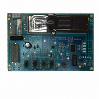
... STEVAL-IHM020V1 demonstration board based on the Introduction The STEVAL-IHM020V1 demonstration board (see the performance of the STCC08, which switch failure mode detector and an AC power switch driver. The device is dedicated to driving IGT AC switches (ACS, ACST and TRIACs), and detecting any switch failures. This solution embeds a switch driver and an AC switch state detector ...
Page 2
Contents Contents 1 Demonstration board introduction . . . . . . . . . . . . . . . . . . . . . . . . . . . . . 4 1.1 Package contents . ...
Page 3
... UM0583 List of figures Figure 1. STEVAL-IHM020V1, STCC08 demonstration board . . . . . . . . . . . . . . . . . . . . . . . . . . . . . . 1 Figure 2. Main components used (top view Figure 3. Main components used (top view Figure 4. STCC08 block diagram description . . . . . . . . . . . . . . . . . . . . . . . . . . . . . . . . . . . . . . . . . . . 6 Figure 5. Application diagram . . . . . . . . . . . . . . . . . . . . . . . . . . . . . . . . . . . . . . . . . . . . . . . . . . . . . . . 6 Figure 6. AC switch failure-detection principle . . . . . . . . . . . . . . . . . . . . . . . . . . . . . . . . . . . . . . . . . . . 8 Figure 7. Measurement points (top layer view Figure 8. STCC08 demonstration board (top view Figure 9 ...
Page 4
Demonstration board introduction 1 Demonstration board introduction 1.1 Package contents The following items are supplied in this package: ● Demonstration board featuring the STCC08 AC switch failure mode detector ● DVD containing user manual, product presentation and datasheets. 1.2 Board ...
Page 5
UM0583 Components on the demonstration board include: ● the STCC08 device (U1) ● the STLITE39F2 MCU (U2). The 8-bit MCU drives the AC switch through the STCC08, analyzes the STCC08 AVF signals and powers LEDs to indicate AC switch failures ...
Page 6
STCC08 description 2 STCC08 description 2.1 Block diagram description Figure 4 shows the block diagram of the STCC08. It includes a “gate driver” block to control the AC switch, a “power switch signal shaping” block used to read the AC ...
Page 7
UM0583 Table 1. STCC08 pin definition Pin Symbol 2.2 Gate driver The STCC08 can control up to 10mA IGT TRIACs, ACST and ACS through a “GATE DRIVER” block designed: ● to drive ...
Page 8
STCC08 description Figure 6. AC switch failure-detection principle VCC/COM VCC/COM switch AC switch Line Line Load Load RShunt RShunt VCC/COM VCC/COM switch AC switch Line Line Load Load RShunt RShunt VCC/COM VCC/COM ...
Page 9
UM0583 Table 2 gives the AC switch state according to the AVF signal and the MCU control (IN). Knowing the IN signal state, the MCU is able to define the AC switch state by analyzing the AVF signal. According to ...
Page 10
Features 3 Features 3.1 ST7LITE39F2 microcontroller The 8-bit MCU used in this board is the ST7LITE39F2. It belongs to the ST7 family of microcontrollers, and offers a large number of features at minimum cost. ● The peripheral hardware requirements are ...
Page 11
UM0583 temperatures, please refer to application note AN2716 to redefine the R STCC08 consumption to redefine the C16 capacitor value. To reduce the surge current when the board is powered Ω R14 resistor is connected in series with ...
Page 12
Using the demonstration board 4 Using the demonstration board 4.1 Load The ACS included in the board can withstand a 0.8 A RMS permanent current ambient temperature of 80 °C. The switch can drive common washing-machine AC ...
Page 13
UM0583 4.3 Getting started Warning: Any measurement equipment must be isolated from the mains before powering the board. To use an oscilloscope with the demonstration board safer to isolate it from the AC line. This prevents electric shocks ...
Page 14
Using the demonstration board ● To operate the STCC08 board correctly and at each test, perform the following procedure first: – Place the “STCC08 CNTRL” switch (SW5) to the “OFF” position – Set the “N DIODE MODE (SW2)” and “P ...
Page 15
UM0583 Figure 9. Short-circuit detection Figure 10. Diode mode detection Figure 11. Open circuit detection Using the demonstration board AVF AC Line Load AVF AC Line ...
Page 16
IEC 61000-4-4 Burst immunity test 5 IEC 61000-4-4 Burst immunity test 5.1 Test conditions ● Ambient temperature: 25 °C ● Relative humidity: 35% ● Test performed in accordance with IEC 61000-4-4 5.2 Demonstration board immunity test The AC line input ...
Page 17
UM0583 data. This maintains the previous switch state, for example, when a RESET occurs due to an EMI problem. If, when checked, the RAM registers are not as expected, a complete initialization procedure is launched. If the RAM area is ...
Page 18
... Conclusion 6 Conclusion The STEVAL-IHM020V1 demonstration board has been developed to: ● Demonstrate the STCC08 failure-detection capabilities ● Show how to connect the STCC08 to an MCU (non-insulated version) ● Give the user the opportunity to evaluate a full ST solution (microcontroller + STCC08). This user manual is intended to help home appliance designers test and evaluate the STCC08 AC switch failure mode detector using the demonstration board ...
Page 19
... UM0583 Appendix A STCC08 demonstration board schematic Figure 13. STEVAL-IHM020V1 demonstration board schematic diagram 2 1 STCC08 demonstration board schematic CNTRL STCC08 15W - Bulb Light - J2 AM01347v1 19/23 ...
Page 20
Bill of materials Appendix B Bill of materials Table 5. Bill of material Ref. Part/value U1 STCC08 U2 ST7LITE39FM6 U3 ACS108-6S R1, R2, R3, R4, R5, R6, 56 kΩ R7, R8 R9, R10, R11, 68 kΩ R12 39 Ω R14 ...
Page 21
UM0583 Table 5. Bill of material (continued) Ref. Part/value LIGHT BULB - 230 V RMS Female J3 connector HE10 - 2x5 F1 Fuse SW1, SW2, Switch SW3, SW4 SW5 Switch TP1, TP2, TP3, TP4, TP5, TP6, ...
Page 22
Revision history Revision history Table 6. Document revision history Date 12-Nov-2008 22/23 Revision 1 Initial release UM0583 Changes ...
Page 23
... UM0583 Information in this document is provided solely in connection with ST products. STMicroelectronics NV and its subsidiaries (“ST”) reserve the right to make changes, corrections, modifications or improvements, to this document, and the products and services described herein at any time, without notice. All ST products are sold pursuant to ST’s terms and conditions of sale. ...