STEVAL-IHT001V1 STMicroelectronics, STEVAL-IHT001V1 Datasheet - Page 9
STEVAL-IHT001V1
Manufacturer Part Number
STEVAL-IHT001V1
Description
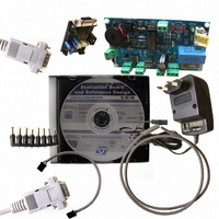
EVAL BOARD THERMO CONTROL REFRIG
Manufacturer
STMicroelectronics
Specifications of STEVAL-IHT001V1
Design Resources
STEVAL-IHT001V1 Gerber Files STEVAL-IHT001V1 Schematic STEVAL-IHT001V1 Bill of Materials
Main Purpose
Reference Design, ARM7 Thermostat for Fridge or Freezer
Embedded
Yes, MCU, 8-Bit
Utilized Ic / Part
ACS102-6, ACS110, ACST6, ST7LITE39F2
Primary Attributes
Compressor, Defrost & Light Controls
Secondary Attributes
Graphical User Interface
Lead Free Status / RoHS Status
Lead free / RoHS Compliant
Other names
497-5514


UM0277
2.3.2
2.3.3
ST7LITE39F2 microcontroller
The MCU used in the thermostat kit is the ST7LITE39F2. It belongs to the ST7LITE39F2
MCU family. It embeds a large number of features at the minimum cost. The peripheral
hardware requirements are then reduced to the minimum:
●
●
In case of MCU firmware change, four options have to be set:
●
●
●
●
Capacitive power supply
To reduce the board price as much as possible, a capacitive power supply is used on the
board. The maximum average current sunk by the board is about 30mA for 4ms gate current
pulse widths (see
for the board to work correctly under typical application conditions (nominal capacitor value,
230V RMS line voltage).
Table 2.
For higher or lower currents, the C3 capacitor can be changed.
allowed average current versus the different C3 capacitor values for typical application
conditions (nominal capacitor value, 230 V
(nominal C3 capacitor value -10%, 198 V
For more information about the design of the capacitive power supply please refer to
Application Note AN1476.
MCU
LEDs
Gate average
current necessary
to control AC
switches
Others (Push
Button, NTC
supply, Buzzer)
Total
No crystal oscillator or external resonator is used. Indeed, the internal RC-oscillator of
the ST7LITE39F2 is used to generate the clock.
No external RESET circuit is used, due to the internal circuit of the ST7LITE39F2.
Software watchdog activation
RC oscillator selection
PLL disabled
Low Voltage Detection selection
Devices
Maximum average current sunk by the board
Table
2.5mA
2.7mA
21mA
4.3mA
30.5mA
Average current
consumption
2). In this case, a 1µF C3 capacitor value should be used in order
Maximum supply current in Run Mode.
LEDs switch ON/OFF alternatively on each AC mains
polarity in order to reduce the current consumption.
R
Switches Q1 (Compressor) and Q2 (Defrost) cannot be
switched ON at the same time. The gate average current is
only defined according to the Q2 (Defrost) and Q3 (Light
Bulb) gate current.
V
R
V
R
(I
f
V
CPU
Buzzer supply current
DD_Max
DD_Max
9
5
15
F
= R
= 390Ω±5% and 4ms gate currents pulses widths
RMS
= 1.6V @ I
= 200Ω±5%
RMS
= 1MHz and V
10
line voltage), for a 50Hz mains frequency.
= 5.5V, R
= 5.5V, R
= R
line voltage) and worst application case
11
F
= 750Ohms±1%
= 4mA, V
DSON_MCU
NTC
= 4mA)
DD
@0°C = 16Ω, R
= 5.5V
Comments
DD_Max
Table 3
= 25Ω, R
Functional description
= 5.5V and
lists the maximum
14
4
= 130Ω±5%,
= 10kΩ±5% and
9/32
Related parts for STEVAL-IHT001V1
Image
Part Number
Description
Manufacturer
Datasheet
Request
R

Part Number:
Description:
BOARD EVAL FOR MEMS SENSORS
Manufacturer:
STMicroelectronics
Datasheet:

Part Number:
Description:
KIT DEV STARTER ST10F276Z5
Manufacturer:
STMicroelectronics
Datasheet:

Part Number:
Description:
BOARD EVAL HDMI $ VIDEO SWITCH
Manufacturer:
STMicroelectronics
Datasheet:

Part Number:
Description:
BOARD DEMO ACCELEROMETER DIL24
Manufacturer:
STMicroelectronics
Datasheet:

Part Number:
Description:
BOARD STLM75/STDS75/ST72F651
Manufacturer:
STMicroelectronics
Datasheet:

Part Number:
Description:
EVAL BOARD 3AXIS MEMS ACCELLRMTR
Manufacturer:
STMicroelectronics
Datasheet:

Part Number:
Description:
BOARD EVAL 8BIT MICRO + TDE1708
Manufacturer:
STMicroelectronics
Datasheet:

Part Number:
Description:
EVAL BOARD A/D TS4657
Manufacturer:
STMicroelectronics
Datasheet:

Part Number:
Description:
BOARD ADAPTER 20DIP LIS3LV02DL
Manufacturer:
STMicroelectronics
Datasheet:

Part Number:
Description:
BOARD DEMO STM8S207R6/LIS331DLH
Manufacturer:
STMicroelectronics
Datasheet:

Part Number:
Description:
STMicroelectronics [RIPPLE-CARRY BINARY COUNTER/DIVIDERS]
Manufacturer:
STMicroelectronics
Datasheet:
Part Number:
Description:
STMicroelectronics [LIQUID-CRYSTAL DISPLAY DRIVERS]
Manufacturer:
STMicroelectronics
Datasheet:
Part Number:
Description:
BOARD EVAL FOR MEMS SENSORS
Manufacturer:
STMicroelectronics
Datasheet: