STEVAL-IHM010V1 STMicroelectronics, STEVAL-IHM010V1 Datasheet - Page 8
STEVAL-IHM010V1
Manufacturer Part Number
STEVAL-IHM010V1
Description
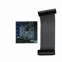
KIT IGBT PWR MODULE CTRL ST7MC
Manufacturer
STMicroelectronics
Type
Motor / Motion Controllers & Driversr
Specifications of STEVAL-IHM010V1
Main Purpose
Power Management, Motor Control
Embedded
Yes, MCU, 8-Bit
Utilized Ic / Part
ST7FMC2S4
Primary Attributes
3-Ph Brushless BLDC, AC & 3-Ph AC Induction (ACIM) Motors
Secondary Attributes
Graphic User Interface, 4 Pots for Runtime Settings, Start/Stop and Reset Buttons
Input Voltage
5 V
Product
Power Management Modules
Silicon Manufacturer
ST Micro
Core Architecture
ARM
Core Sub-architecture
ARM7TDMI
Silicon Core Number
ST7
Silicon Family Name
ST7MCx
Kit Contents
Board
Lead Free Status / RoHS Status
Lead free / RoHS Compliant
For Use With/related Products
ST7MC
Other names
497-8400


Safety and operating instructions
2
2.1
2.2
2.3
2.4
2.5
8/48
Safety and operating instructions
General
During assembly and operation, the IGBT power module eval kit poses several inherent
hazards, including bare wires, moving or rotating parts, and hot surfaces. There is danger of
serious personal injury and damage to property, if it is improperly used or installed
incorrectly.
All operations involving transportation, installation and use, as well as maintenance are to
be carried out by skilled technical personnel (national accident prevention rules must be
observed). For the purposes of these basic safety instructions, "skilled technical personnel"
are suitably qualified people who are familiar with the installation, use, and maintenance of
power electronic systems.
Reference design board intended use
The IGBT power module eval kit boards are components designed for demonstration
purposes only, and shall not be used for electrical installation or machinery. The technical
data as well as information concerning the power supply conditions shall be taken from the
documentation and strictly observed.
Reference design board installation
The installation and cooling of the reference design boards shall be in accordance with the
specifications and the targeted application (see
●
●
●
Electronic connection
Applicable national accident prevention rules must be followed when working on the main
power supply with a motor drive. The electrical installation shall be completed in accordance
with the appropriate requirements (e.g., cross-sectional areas of conductors, fusing, PE
connections. For further information see
Reference design board operation
A system architecture which supplies power to the IGBT power module eval kit boards shall
be equipped with additional control and protective devices in accordance with the applicable
safety requirements (e.g., compliance with technical equipment and accident prevention
rules).
The motor drive converters shall be protected against excessive strain. In particular, no
components are to be bent, or isolating distances altered during the course of
transportation or handling.
No contact shall be made with other electronic components and contacts.
The boards contain electrostatically sensitive components that are prone to damage
through improper use. Electrical components must not be mechanically damaged or
destroyed (to avoid potential health risks).
Section 7: Motor control
Section 7: Motor control
demonstration.
demonstration).
UM0430
Related parts for STEVAL-IHM010V1
Image
Part Number
Description
Manufacturer
Datasheet
Request
R

Part Number:
Description:
BOARD EVAL FOR MEMS SENSORS
Manufacturer:
STMicroelectronics
Datasheet:

Part Number:
Description:
KIT DEV STARTER ST10F276Z5
Manufacturer:
STMicroelectronics
Datasheet:

Part Number:
Description:
BOARD EVAL HDMI $ VIDEO SWITCH
Manufacturer:
STMicroelectronics
Datasheet:

Part Number:
Description:
BOARD DEMO ACCELEROMETER DIL24
Manufacturer:
STMicroelectronics
Datasheet:

Part Number:
Description:
BOARD STLM75/STDS75/ST72F651
Manufacturer:
STMicroelectronics
Datasheet:

Part Number:
Description:
EVAL BOARD 3AXIS MEMS ACCELLRMTR
Manufacturer:
STMicroelectronics
Datasheet:

Part Number:
Description:
BOARD EVAL 8BIT MICRO + TDE1708
Manufacturer:
STMicroelectronics
Datasheet:

Part Number:
Description:
EVAL BOARD A/D TS4657
Manufacturer:
STMicroelectronics
Datasheet:

Part Number:
Description:
BOARD ADAPTER 20DIP LIS3LV02DL
Manufacturer:
STMicroelectronics
Datasheet:

Part Number:
Description:
BOARD DEMO STM8S207R6/LIS331DLH
Manufacturer:
STMicroelectronics
Datasheet:

Part Number:
Description:
STMicroelectronics [RIPPLE-CARRY BINARY COUNTER/DIVIDERS]
Manufacturer:
STMicroelectronics
Datasheet:
Part Number:
Description:
STMicroelectronics [LIQUID-CRYSTAL DISPLAY DRIVERS]
Manufacturer:
STMicroelectronics
Datasheet:
Part Number:
Description:
BOARD EVAL FOR MEMS SENSORS
Manufacturer:
STMicroelectronics
Datasheet: