STEVAL-IHM010V1 STMicroelectronics, STEVAL-IHM010V1 Datasheet - Page 40
STEVAL-IHM010V1
Manufacturer Part Number
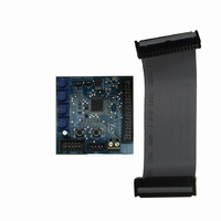
STEVAL-IHM010V1
Description
KIT IGBT PWR MODULE CTRL ST7MC
Manufacturer
STMicroelectronics
Type
Motor / Motion Controllers & Driversr
Specifications of STEVAL-IHM010V1
Main Purpose
Power Management, Motor Control
Embedded
Yes, MCU, 8-Bit
Utilized Ic / Part
ST7FMC2S4
Primary Attributes
3-Ph Brushless BLDC, AC & 3-Ph AC Induction (ACIM) Motors
Secondary Attributes
Graphic User Interface, 4 Pots for Runtime Settings, Start/Stop and Reset Buttons
Input Voltage
5 V
Product
Power Management Modules
Silicon Manufacturer
ST Micro
Core Architecture
ARM
Core Sub-architecture
ARM7TDMI
Silicon Core Number
ST7
Silicon Family Name
ST7MCx
Kit Contents
Board
Lead Free Status / RoHS Status
Lead free / RoHS Compliant
For Use With/related Products
ST7MC
Other names
497-8400


Motor control demonstration
Table 14.
7.6.7
7.7
40/48
P2
P3
P4
P1
P2
P3
P4
12
13
14
sets the value of falling delay coefficient from 0 to
sets the value of falling delay coefficient from 0 to
sets the value of rising delay coefficient from 0 to
sets the value of rising delay coefficient from 0 to
sets the current reference value from 0 A to
Potentiometer functionality based on open/closed loop driving strategy (continued)
If during the configuration using GUI , the "From RV1" control has been unchecked, the
value of duty cycle (or the value of current reference) is not set by P1, but has a fixed value.
If during the configuration using GUI, the "From RV2 - RV3" control has been unchecked,
the value of the rising delay coefficient and the value of the falling delay coefficient are not
set by P2 and P3, but have fixed values.
The maximum duty cycle allowed in voltage mode depends on the value of PWM frequency
and the value of PWM min off time set by the GUI.
The maximum current allowed has been set to 4.1A. (see
maximum current allowed by
Stopping the motor (LED behavior)
Push the Start/Stop button to stop the motor. The LEDs toggle from green to red to indicate
"idle state"
It is possible to configure the system to drive the BLDC motor in current mode and or in
closed loop and restart the demonstration from
(trapezoidal)"
Driving the BLDC Motor (trapezoidal - sensored)
Before proceeding with the motor control demonstration, the power board STEVAL-
IHM011V1 must be set up to drive "3 Phase BLAC/DC (trapezoidal - sensored)" settings as
described in the power board user manual.
Let's start the demonstration driving the brushless permanent magnet motor in voltage
mode - open loop - sensor 60° . At this point please check that the control board has been
maximum current allowed.
Open loop
not used
not used
settings.
255
255
255
255
GUI.)
Current mode
Voltage mode
sets the value of falling delay coefficient from 0 to 255
sets the value of falling delay coefficient from 0 to 255
sets the value of rising delay coefficient from 0 to 255
sets the value of rising delay coefficient from 0 to 255
sets the target rotor frequency value from minimum
Section 7.4.4: "3 Phase BLAC/DC (trapezoidal)"
Section 7.4.4: "3 Phase BLAC/DC
value to Maximum value configured (see
Section 7.4.10: Changing the
Closed loop
not used
not used
settings)
UM0430
Related parts for STEVAL-IHM010V1
Image
Part Number
Description
Manufacturer
Datasheet
Request
R

Part Number:
Description:
BOARD EVAL FOR MEMS SENSORS
Manufacturer:
STMicroelectronics
Datasheet:

Part Number:
Description:
KIT DEV STARTER ST10F276Z5
Manufacturer:
STMicroelectronics
Datasheet:

Part Number:
Description:
BOARD EVAL HDMI $ VIDEO SWITCH
Manufacturer:
STMicroelectronics
Datasheet:

Part Number:
Description:
BOARD DEMO ACCELEROMETER DIL24
Manufacturer:
STMicroelectronics
Datasheet:

Part Number:
Description:
BOARD STLM75/STDS75/ST72F651
Manufacturer:
STMicroelectronics
Datasheet:

Part Number:
Description:
EVAL BOARD 3AXIS MEMS ACCELLRMTR
Manufacturer:
STMicroelectronics
Datasheet:

Part Number:
Description:
BOARD EVAL 8BIT MICRO + TDE1708
Manufacturer:
STMicroelectronics
Datasheet:

Part Number:
Description:
EVAL BOARD A/D TS4657
Manufacturer:
STMicroelectronics
Datasheet:

Part Number:
Description:
BOARD ADAPTER 20DIP LIS3LV02DL
Manufacturer:
STMicroelectronics
Datasheet:

Part Number:
Description:
BOARD DEMO STM8S207R6/LIS331DLH
Manufacturer:
STMicroelectronics
Datasheet:

Part Number:
Description:
STMicroelectronics [RIPPLE-CARRY BINARY COUNTER/DIVIDERS]
Manufacturer:
STMicroelectronics
Datasheet:
Part Number:
Description:
STMicroelectronics [LIQUID-CRYSTAL DISPLAY DRIVERS]
Manufacturer:
STMicroelectronics
Datasheet:
Part Number:
Description:
BOARD EVAL FOR MEMS SENSORS
Manufacturer:
STMicroelectronics
Datasheet: