EVAL6569 STMicroelectronics, EVAL6569 Datasheet - Page 9

EVAL6569
Manufacturer Part Number
EVAL6569
Description
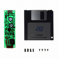
BOARD EVAL LIGHTING L6569
Manufacturer
STMicroelectronics
Type
Charge Pumpsr
Datasheet
1.EVAL6569.pdf
(14 pages)
Specifications of EVAL6569
Mfg Application Notes
L6569, AN880 App Note
Main Purpose
Lighting, Ballast Control
Embedded
No
Utilized Ic / Part
L6569
Primary Attributes
18 W, Optimized for a CF18DT/E/830, 120 or 230 VAC
Secondary Attributes
Preheating Done with a PTC
Input Voltage
230 V
Product
Power Management Modules
Supply Current
0.17 A
Lead Free Status / RoHS Status
Lead free / RoHS Compliant
For Use With/related Products
L6569
Other names
497-4738
line voltage V
starts. The ballast has to start directly with its
nominal conditions to remove any transient oscil-
lation. Hence the operation runs in ZVS mode
with no spurious lamp ignition. This situation does
not occur with the saturable transformer drive, be-
cause the saturation limits naturally the current by
increasing the frequency.
In the example the resonant capacitors are pre-
set to be compatible with the choke current rise
(see figure 19). The blocking capacitor is pre-
charged to approximately half V
resistors, and the lower Mosfet also discharges
the resonant capacitor to ground (see figure 20).
Therefore the blocking capacitor never goes
above 2/3 of the line voltage V
the operation is safe in ZVS mode. The L6569 is
here preferred to the L6569A, because the lower
Figure 19: Waveforms of the choke current and
Mosfet is on at power-up.
Figure 20: Configuration of the resonant network during the initialization of the driver.
5 s/dv ; 50 V/dv ; 0.5 A/dv
the capacitor voltages in steady state
preheat.
V
BI
VS<UVLO
DC
IDEAL INITIAL TIME
L6569
is applied when the oscillator
I
I
DC
DC
V
(250V rating),
B
by 2 biasing
ON
2.4 mH
2 x 180 k
GND
GND
V
B
The lamp removal protection
Used in TL ballast, the lamp removal protection is
frequently also requested in the "plug-in" CFL bal-
last . Depending of the topology and the preheat
mode, the lamp removal behaves as:
When the circuit is open, the choke is not sup-
plied. The MOSFETs turn off slowly generating
bridge cross conduction, and undesirable dissipa-
tion losses (see figure 21). The detection stops
the switching to eliminate the cross conduction.
Figure 21: Drain current and voltage STP8NA50
V
V
I
- a noload resonant mode when the choke and
- an open circuit mode when the lamp filaments
D
D
GS
the capacitor are still connected to the in-
verter ; a required overcurrent protection in-
creases the frequency to reduce the current;
are inserted in the resonant circuit.
I
MOSFET operating with noload.
100 ns/dv ; 50 V/dv ; 5V/dv ; 1 A/dv
I
AN880 APPLICATION NOTE
100 nF
I
D
= 2 A peak
V
BI
4nF
GND
GND
GND
9/14


