EVAL6569 STMicroelectronics, EVAL6569 Datasheet - Page 11
EVAL6569
Manufacturer Part Number
EVAL6569
Description
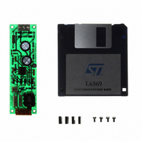
BOARD EVAL LIGHTING L6569
Manufacturer
STMicroelectronics
Type
Charge Pumpsr
Datasheet
1.EVAL6569.pdf
(14 pages)
Specifications of EVAL6569
Mfg Application Notes
L6569, AN880 App Note
Main Purpose
Lighting, Ballast Control
Embedded
No
Utilized Ic / Part
L6569
Primary Attributes
18 W, Optimized for a CF18DT/E/830, 120 or 230 VAC
Secondary Attributes
Preheating Done with a PTC
Input Voltage
230 V
Product
Power Management Modules
Supply Current
0.17 A
Lead Free Status / RoHS Status
Lead free / RoHS Compliant
For Use With/related Products
L6569
Other names
497-4738


APPENDIX A: CFL DEMONSTRATION BOARD
WITH THE L6569
A demonstration board was developed as an ex-
ample for Compact Fluorescent Lamp ballast. It is
optimised for a CF18DT/E/830 18W lamp from
Osram-Sylvania. Using the L6569 the circuit
achieves preheat, ignition and normal lamp op-
eration. The power transistors are two STD3NA50
500V-3 MOSFETs in I-PACK package.
Board description
The three sections of the board are an AC input
rectifier, the half bridge inverter, and the resonant
ballast. By changing the connection on the input
mains, the ballast can operate either on 120 Vac
mains with a voltage doubler rectification, or on
230 Vac mains with a full wave rectification. The
input resistor R
charging the bulk capacitors. The L6569 operates
with a single 50 kHz switching frequency pro-
grammed by R
synchronize the oscillator to keep the switching in
ZVS mode. The control circuit requires 4.5 mA to
supply the I.C., the MOS gate drives, and the os-
cillator. Its supply delivers at least 6.5 mA as de-
scribed in appendix B. The start up resistor also
balances the voltage across the two bulk capaci-
tors.
Figure 23. CFL ballast diagram for a 18W
CFD18T/E lamp with 120/230 Vac inputs.
Figure 23.
220V
110V
N
4 x 1N4006
R1 15 1W
D7
D6
L1=2.4mH core TH LCC E2006-B4 Ref also VOGH 575 0409200 2.4mH
C7-C8=PS8n2J H3 630-2A TH
(*) Polypropylene, Capacitors 630V rated V
D4
D5
120K
1/2W
R8
4
47 F
250V
1
C5
and C
limits the initial inrush current
R5 100K
1/2W
4.7 F
47 F
250V
25V
C2
C3
1
. Two fast diodes D
1N4148
1/4W
ZPD 18V
27K
R4
D8
D1
L
560pF
50V
C1
R6 47 1/4W
RF
CF
V
S
L6569
2
C9 470pF 630V
& D
3
(*)
BOOT
HVG
OUT
LVG
GND
C4100nF 50V
R2 22 1/4W
R3 22 1/4W
The resonant ballast
The value of the choke (L
tors (C
the lamp ignition voltage and the nominal lamp
current. During the ignition the lamp impedance is
essentially infinite, and the filaments resistance is
only the serial load. To generate the ignition volt-
age, the switching frequency is set close to the
resonance frequency. In normal operation the
choke resonates with the capacitors C
(parallel loading), but also with the decoupling ca-
pacitor C
heat uses a 150
cient thermistor. Inserted in the capacitive series
(C
ment current during the initial 0.8 s (reference:
307C1253BHEAB from CERA-MITE).
Basic ballast electrical characteristics
Input voltage: 120 or 230 Vac by input connec-
tions change
Switching frequency: 50kHz
Average dc line voltage range: Vdc from 260 to 355
Nominal supply current: 0.17A rms @ 310 Vdc
Nominal output power: 17W
Minimum ignition voltage: 700V peak @ 260 Vdc
Nominal preheat current: 0.45 Arms during 0.8s
@ 310 Vdc
7
D96IN419C
& C
7
R10 10K
& C
8
1/4W
6
), the PTC produces a 0.45 Arms fila-
(serial loading). The current mode pre-
8
) in parallel with the lamp determine
BYW100-100
STD4NK50
STD4NK50
D3 BYW100-100
AN880 APPLICATION NOTE
Q1
Q2
D2
180K
1/4W
R7
Positive Temperature Coeffi-
100nF
180K
1/4W
250V
R9
C6
L1=2.4mH
SYLVANIA DELUX T/E 18W
1
) and the two capaci-
CFL LAMP
8.2nF
8.2nF
630V
630V
C7
C8
(*)
(*)
7
& C
PTC 150
11/14
350V
RV1
8
Related parts for EVAL6569
Image
Part Number
Description
Manufacturer
Datasheet
Request
R

Part Number:
Description:
STMicroelectronics [RIPPLE-CARRY BINARY COUNTER/DIVIDERS]
Manufacturer:
STMicroelectronics
Datasheet:
Part Number:
Description:
STMicroelectronics [LIQUID-CRYSTAL DISPLAY DRIVERS]
Manufacturer:
STMicroelectronics
Datasheet:

Part Number:
Description:
BOARD EVAL FOR MEMS SENSORS
Manufacturer:
STMicroelectronics
Datasheet:
Part Number:
Description:
NPN TRANSISTOR POWER MODULE
Manufacturer:
STMicroelectronics
Datasheet:
Part Number:
Description:
TURBOSWITCH ULTRA-FAST HIGH VOLTAGE DIODE
Manufacturer:
STMicroelectronics
Datasheet:
Part Number:
Description:
Manufacturer:
STMicroelectronics
Datasheet:
Part Number:
Description:
DIODE / SCR MODULE
Manufacturer:
STMicroelectronics
Datasheet:
Part Number:
Description:
DIODE / SCR MODULE
Manufacturer:
STMicroelectronics
Datasheet:
Part Number:
Description:
Search -----> STE16N100
Manufacturer:
STMicroelectronics
Datasheet:
Part Number:
Description:
Search ---> STE53NA50
Manufacturer:
STMicroelectronics
Datasheet:
Part Number:
Description:
NPN Transistor Power Module
Manufacturer:
STMicroelectronics
Datasheet:
Part Number:
Description:
DIODE / SCR MODULE
Manufacturer:
STMicroelectronics
Datasheet: