AD9520-4/PCBZ Analog Devices Inc, AD9520-4/PCBZ Datasheet - Page 2
AD9520-4/PCBZ
Manufacturer Part Number
AD9520-4/PCBZ
Description
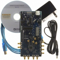
BOARD EVAL FOR AD9520-4
Manufacturer
Analog Devices Inc
Specifications of AD9520-4/PCBZ
Design Resources
Synchronizing Multiple AD9910 1 GSPS Direct Digital Synthesizers (CN0121) Phase Coherent FSK Modulator (CN0186)
Main Purpose
Timing, Clock Generator
Embedded
No
Utilized Ic / Part
AD9520-4
Primary Attributes
1.4 ~ 1.8 GHz Output Frequency
Secondary Attributes
Accepts CMOS, LVDS, or LVPECL References Up to 250 MHz
Silicon Manufacturer
Analog Devices
Application Sub Type
PLL Clock Synthesizer
Kit Application Type
Clock & Timing
Silicon Core Number
AD9520-0, AD9520-2, AD9520-2
Silicon Family Name
AD9520-X
Rohs Compliant
Yes
Lead Free Status / RoHS Status
Lead free / RoHS Compliant


AD9520-4
TABLE OF CONTENTS
Features .............................................................................................. 1
Applications ....................................................................................... 1
General Description ......................................................................... 1
Functional Block Diagram .............................................................. 1
Revision History ............................................................................... 3
Specifications ..................................................................................... 4
Absolute Maximum Ratings .......................................................... 17
Pin Configuration and Function Descriptions ........................... 18
Typical Performance Characteristics ........................................... 21
Terminology .................................................................................... 26
Detailed Block Diagram ................................................................ 27
Theory of Operation ...................................................................... 28
Power Supply Requirements ....................................................... 4
PLL Characteristics ...................................................................... 4
Clock Inputs .................................................................................. 7
Clock Outputs ............................................................................... 7
Timing Characteristics ................................................................ 8
Clock Output Additive Phase Noise (Distribution Only; VCO
Divider Not Used) ...................................................................... 10
Clock Output Absolute Phase Noise (Internal VCO Used) .. 11
Clock Output Absolute Time Jitter (Clock Generation Using
Internal VCO) ............................................................................. 11
Clock Output Absolute Time Jitter (Clock Cleanup Using
Internal VCO) ............................................................................. 11
Clock Output Absolute Time Jitter (Clock Generation Using
External VCXO) ......................................................................... 12
Clock Output Additive Time Jitter (VCO Divider Not Used)
Clock Output Additive Time Jitter (VCO Divider Used) ..... 13
Serial Control Port—SPI Mode ................................................ 13
Serial Control Port—I2C Mode ................................................ 14
PD , SYNC , and RESET Pins ..................................................... 15
Serial Port Setup Pins: SP1, SP0 ............................................... 15
LD, STATUS, REFMON Pins.................................................... 15
Power Dissipation ....................................................................... 16
Thermal Resistance .................................................................... 17
ESD Caution ................................................................................ 17
Operational Configurations ...................................................... 28
....................................................................................................... 12
Timing Diagrams ..................................................................... 9
Mode 0: Internal VCO and Clock Distribution ................. 28
Rev. 0 | Page 2 of 84
Zero Delay Operation ................................................................ 43
Clock Distribution ..................................................................... 44
Reset Modes ................................................................................ 49
Mode 1: Clock Distribution or External
VCO <1600 MHz ................................................................... 30
Mode 2: High Frequency Clock Distribution—CLK or
External VCO > 1600 MHz .................................................. 32
Phase-Locked Loop (PLL) .................................................... 34
Configuration of the PLL ...................................................... 34
Phase Frequency Detector (PFD) ........................................ 34
Charge Pump (CP) ................................................................. 35
On-Chip VCO ........................................................................ 35
PLL External Loop Filter ....................................................... 35
PLL Reference Inputs ............................................................. 35
Reference Switchover ............................................................. 36
Reference Divider R ............................................................... 36
VCXO/VCO Feedback Divider N: P, A, B, R ..................... 36
Digital Lock Detect (DLD) ................................................... 38
Analog Lock Detect (ALD) ................................................... 38
Current Source Digital Lock Detect (CSDLD) .................. 38
External VCXO/VCO Clock Input (CLK/ CLK ) ................ 39
Holdover .................................................................................. 39
Manual Holdover Mode ........................................................ 39
Automatic/Internal Holdover Mode .................................... 39
Frequency Status Monitors ................................................... 41
VCO Calibration .................................................................... 42
Internal Zero Delay Mode ..................................................... 43
External Zero Delay Mode .................................................... 43
Operation Modes ................................................................... 44
CLK or VCO Direct-to-LVPECL Outputs .......................... 44
Clock Frequency Division ..................................................... 45
VCO Divider ........................................................................... 45
Channel Dividers ................................................................... 45
Synchronizing the Outputs—SYNC Function ................... 47
LVPECL Output Drivers ....................................................... 48
CMOS Output Drivers .......................................................... 49
Power-On Reset ...................................................................... 49
Hardware Reset via the RESET Pin ..................................... 49
Soft Reset via the Serial Port ................................................. 49
Soft Reset to Settings in EEPROM when EEPROM Pin = 0 via
the Serial Port ......................................................................... 49
Related parts for AD9520-4/PCBZ
Image
Part Number
Description
Manufacturer
Datasheet
Request
R

Part Number:
Description:
12/24 Channel Clock Gen 2,0GH
Manufacturer:
Analog Devices Inc
Datasheet:

Part Number:
Description:
12/24 Channel Clock Gen 2,0GH
Manufacturer:
Analog Devices Inc
Datasheet:
Part Number:
Description:
12/24 Channel Clock Gen 2,0GH
Manufacturer:
Analog Devices Inc
Datasheet:
Part Number:
Description:
12/24 Channel Clock Gen 2,0GH
Manufacturer:
Analog Devices Inc
Datasheet:
Part Number:
Description:
12/24 Channel Clock Gen 2,0GH
Manufacturer:
Analog Devices Inc
Datasheet:
Part Number:
Description:
Clock IC With 2.8GHz On-chip VCO
Manufacturer:
Analog Devices Inc
Datasheet:
Part Number:
Description:
Lock IC With 2.8GHz On-chip VCO
Manufacturer:
Analog Devices Inc
Datasheet:
Part Number:
Description:
12/24 Channel Clock Gen 2,5 GHz VCO
Manufacturer:
Analog Devices Inc
Datasheet:
Part Number:
Description:
12/24 Channel Clock Distribution W/ On-C
Manufacturer:
Analog Devices Inc
Datasheet:
Part Number:
Description:
12/24 Channel Clock Gen 2,25GH
Manufacturer:
Analog Devices Inc
Datasheet:
Part Number:
Description:
12/24 Channel Clock Distribution W/ On-C
Manufacturer:
Analog Devices Inc
Datasheet:
Part Number:
Description:
12/24 Channel Clock Distribution W/ On-C
Manufacturer:
Analog Devices Inc
Datasheet:
Part Number:
Description:
Clock IC With 1.6GHz On-chip VCO
Manufacturer:
Analog Devices Inc
Datasheet:
Part Number:
Description:
Clock IC With 1.6GHz On-chip VCO
Manufacturer:
Analog Devices Inc
Datasheet:
Part Number:
Description:
12/24-Output Clock Generator
Manufacturer:
Analog Devices Inc
Datasheet: