RDK-128 Power Integrations, RDK-128 Datasheet - Page 7
RDK-128
Manufacturer Part Number
RDK-128
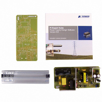
Description
KIT REF DESIGN 36-72W MOTOR DRVR
Manufacturer
Power Integrations
Specifications of RDK-128
Main Purpose
Power Management, Motor Control
Embedded
No
Utilized Ic / Part
PKS606
Primary Attributes
Variable Speed 12V 36W DC Motor, 90 ~ 265 VAC
Secondary Attributes
External Potentiometer or Variable DC Voltage Speed Control
Lead Free Status / RoHS Status
Not applicable / Not applicable
Other names
596-1198


16-Aug-07
RDR-128 36 W, 72 W Peak Variable Output Power Supply
4 Circuit Description
The motor drive power supply shown in Figure 1 is a switch mode power supply design
utilizing the flyback topology.
4.1 Input EMI Filtering
Differential mode EMI filtering is provided by X-capacitor C3. Y-capacitors C1, C2, C10
and C12, together with the common-mode choke L1, provide common-mode EMI
filtering. Additionally the transformer E-Shields™, together with the frequency jittering
features, provide adequate EMI margins.
4.2 PeakSwitch Primary
Fuse F1 protects the power supply from a catastrophic failure due to a short circuit fault.
A high voltage DC bus is created from the AC line voltage by the full-wave rectifier
formed by diodes D1-D4. Capacitor C4 smoothes and filters the rectified AC voltage.
The PKS606YN (U1) integrates a high voltage MOSFET, along with startup and all
necessary control circuitry.
During the MOSFET’s on-time, current flows through the primary of transformer T1,
storing energy in the transformer core.
During the turn off event, the voltage across the primary winding reverses. A voltage
equal to the sum of DC bus voltage and the reflected output voltage (VOR) appears
across the DRAIN and SOURCE of the PeakSwitch, with an additional spike generated
by the leakage inductance. A primary clamp circuit formed by D6, VR1, R3 and C5 limits
this voltage and resets the leakage energy prior to the next switching cycle.
Diode D7 rectifies the supply’s bias winding while capacitor C9 provides DC filtering.
This bias supply is connected to the PeakSwitch’s BP pin via R7, which powers the
device during normal operation.
4.3 Under-voltage Protection and Fast AC Reset circuit
Under-voltage shutdown is implemented by a separate line rectifying diode, D5, which
charges capacitor C7.
Resistors R5 and R6 program the UV start-up voltage to
approximately 104 VDC, which is the DC voltage across C7, at which a current equal to
25 µA flows into the EN/UV pin.
This separate AC line sense network (formed by D5, C7) allows the PeakSwitch to
identify the cause of a fault condition. If the input voltage is above the under-voltage
threshold and the EN/UV pin has not been pulled low for 30 ms, a fault condition is
assumed, and the PeakSwitch latches off. Once the supply is latched off, the AC line
voltage must be removed to allow capacitor C7 to discharge and allow the current into
the EN/UV pin to fall below 25 µA.
Power Integrations
Tel: +1 408 414 9200 Fax: +1 408 414 9201
Page 7 of 32
www.powerint.com
Related parts for RDK-128
Image
Part Number
Description
Manufacturer
Datasheet
Request
R

Part Number:
Description:
KIT REF DESIGN FOR LNK457D
Manufacturer:
Power Integrations
Datasheet:

Part Number:
Description:
REFERENCE DESIGN LINKSWITCH-PH
Manufacturer:
Power Integrations
Datasheet:

Part Number:
Description:
KIT REF DESIGN FOR LNK403EG
Manufacturer:
Power Integrations
Datasheet:

Part Number:
Description:
KIT REF DESIGN FOR LNK406EG
Manufacturer:
Power Integrations
Datasheet:

Part Number:
Description:
KIT REF DESIGN LINKSWITCH-CV
Manufacturer:
Power Integrations
Datasheet:

Part Number:
Description:
KIT REF DESIGN LINKSWITCH 2
Manufacturer:
Power Integrations
Datasheet:

Part Number:
Description:
Specifications: Family: Eval Boards - DC/DC & AC/DC (Off-Line) SMPS ; Series: HiperLCS™ ; Main Purpose: DC/DC, Step Down ; Outputs and Type: 1, Isolated ; Power - Output: 150W ; Voltage - Output: 24V ; Current - Output: 6.25A ; Voltage - Input:
Manufacturer:
Power Integrations, Inc.
Datasheet:

Part Number:
Description:
KIT DESIGN REF TINYSWITCH-III
Manufacturer:
Power Integrations
Datasheet:

Part Number:
Description:
KIT DESIGN REF LINKSWITCH LP
Manufacturer:
Power Integrations
Datasheet:

Part Number:
Description:
KIT REF DESIGN LED LINKSWITCH TN
Manufacturer:
Power Integrations
Datasheet:
Part Number:
Description:
KIT REF DESIGN FOR LNK457D
Manufacturer:
Power Integrations
Datasheet:
Part Number:
Description:
REFERENCE DESIGN LINKSWITCH-PH
Manufacturer:
Power Integrations
Datasheet:
Part Number:
Description:
Specifications: Manufacturer: Power Integrations ; Output Voltage: 380 VDC ; Input / Supply Voltage (Max): 264 VAC ; Input / Supply Voltage (Min): 90 VAC ; Mounting Style: Through Hole ; Output Current: 0.913 A ; Output Power: 347 W
Manufacturer:
Power Integrations, Inc.
Part Number:
Description:
Specifications: Family: Eval Boards - DC/DC & AC/DC (Off-Line) SMPS ; Series: HiperLCS™ ; Main Purpose: DC/DC, Step Down ; Outputs and Type: 1, Isolated ; Power - Output: 150W ; Voltage - Output: 24V ; Current - Output: 6.25A ; Voltage - Input:
Manufacturer:
Power Integrations, Inc.
Datasheet: