EVAL-ADUM4160EBZ Analog Devices Inc, EVAL-ADUM4160EBZ Datasheet - Page 4
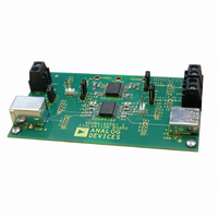
EVAL-ADUM4160EBZ
Manufacturer Part Number
EVAL-ADUM4160EBZ
Description
EVALUATION MODULE FOR ADUM4160
Manufacturer
Analog Devices Inc
Series
iCoupler®r
Datasheets
1.ADUM4160BRWZ-RL.pdf
(16 pages)
2.EVAL-ADUM4160EBZ.pdf
(8 pages)
3.EVAL-ADUM4160EBZ.pdf
(14 pages)
Specifications of EVAL-ADUM4160EBZ
Main Purpose
Interface, Digital Isolator
Embedded
No
Utilized Ic / Part
ADuM4160
Primary Attributes
USB Bidirectional Isolation
Secondary Attributes
3.1 V ~ 5.5 V Supply
Silicon Manufacturer
Analog Devices
Application Sub Type
USB Port Isolator
Kit Application Type
Interface
Silicon Core Number
ADuM4160
Lead Free Status / RoHS Status
Lead free / RoHS Compliant
Lead Free Status / RoHS Status
Lead free / RoHS Compliant, Lead free / RoHS Compliant
Other names
Q4508819


ADuM4160
Parameter
1
2
3
PACKAGE CHARACTERISTICS
Table 2.
Parameter
Resistance (Input to Output)
Capacitance (Input to Output)
Input Capacitance
IC Junction-to-Ambient Thermal Resistance
1
2
REGULATORY INFORMATION
The ADuM4160 is approved by the organizations listed in Table 3. Refer to Table 8 and the Insulation Lifetime section for details
regarding recommended maximum working voltages for specific cross-isolation waveforms and insulation levels.
Table 3.
UL
Recognized under 1577 component
recognition program
Single Protection
5000 V rms Isolation Voltage
File E214100
1
2
The supply current values for the device running at a fixed continuous data rate at 50% duty cycle alternating J and K states. Supply current values are specified with
Propagation delay of the low speed DD+ to UD+ or DD − to UD− in either signal direction is measured from the 50% level of the rising or falling edge, to the 50% level
of the rising or falling edge of the corresponding output signal.
CM
that can be sustained while maintaining V
magnitude is the range over which the common mode is slewed.
Device is considered a 2-terminal device; Pin 1, Pin 2, Pin 3, Pin 4, Pin 5, Pin 6, Pin 7, and Pin 8 are shorted together and Pin 9, Pin 10, Pin 11, Pin 12, Pin 13, Pin 14,
Pin 15, and Pin 16 are shorted together.
Input capacitance is from any input data pin to ground.
In accordance with UL 1577, each ADuM4160 is proof tested by applying an insulation test voltage ≥ 6000 V rms for 1 sec (current leakage detection limit = 10 µA).
In accordance with DIN V VDE V 0884-10, each ADuM4160 is proof tested by applying an insulation test voltage ≥1050 V peak for 1 sec (partial discharge detection
limit = 5 pC). The * marking branded on the component designates DIN V VDE V 0884-10 approval.
USB-compliant load present.
For All Operating Modes
H
Common-Mode Transient Immunity
is the maximum common-mode voltage slew rate that can be sustained while maintaining V
At Logic High Output
At Logic Low Output
2
1
3
1
3
1
O
< 0.8 V. The common-mode voltage slew rates apply to both rising and falling common-mode voltage edges. The transient
CSA
Approved under CSA Component
Acceptance Notice #5A
Basic insulation per CSA 60950-1-03 and IEC 60950-1,
600 V rms (848 V peak) maximum working voltage
Reinforced insulation per CSA 60950-1-03 and IEC
60950-1, 380 V rms (537 V peak) maximum working
voltage
Reinforced insulation per IEC 60601-1 125 V rms (176 V
peak) maximum working voltage
File 205078
Symbol
|CM
|CM
H
L
|
|
Symbol
R
C
C
θ
I-O
JA
Rev. B | Page 4 of 16
I-O
I
Min
25
25
Min
Typ
35
35
O
Typ
10
2.2
4.0
45
> 0.8 V
12
Max
DD2
. CM
Max
L
Unit
kV/µs V
kV/µs V
is the maximum common-mode voltage slew rate
VDE
Certified according to DIN V VDE V
0884-10 (VDE V 0884-10):2006-12
Reinforced insulation, 846 V peak
File 2471900-4880-0001
Unit
Ω
pF
pF
°C/W
Test Conditions
V
800 V
1000 V, transient magnitude = 800 V
UD+
CM
UD+
= 1000 V, transient magnitude =
, V
, V
UD−
UD−
Test Conditions
f = 1 MHz
Thermocouple located at
center of package underside
, V
, V
DD+
DD+
, V
, V
DD−
DD−
= V
= 0 V, V
DD1
or V
CM
2
=
DD2
,
Related parts for EVAL-ADUM4160EBZ
Image
Part Number
Description
Manufacturer
Datasheet
Request
R

Part Number:
Description:
EVAL BD For QSOP & SOIC16 Dig Isolators
Manufacturer:
Analog Devices Inc
Datasheet:

Part Number:
Description:
IC, ADJ LDO REG, 1.5V TO 5V 250mA MSOP-8
Manufacturer:
Vishay
Datasheet:

Part Number:
Description:
IC, ADJ LDO REG, 1.5V TO 5V 0.6A 8-TSSOP
Manufacturer:
Vishay
Datasheet:
Part Number:
Description:
IC, ADJ LDO REG, 1.5V TO 5V 250mA MSOP-8
Manufacturer:
Vishay
Datasheet:

Part Number:
Description:
IC ADJ LDO REG 1.5V TO 5V 150mA 5-SOT-23
Manufacturer:
Vishay
Datasheet:

Part Number:
Description:
BOARD EVAL AS1324-AD
Manufacturer:
austriamicrosystems
Datasheet:
Part Number:
Description:
IC, ADJ LDO REG, 1.5V TO 5V 0.6A 8-TSSOP
Manufacturer:
Vishay
Datasheet:

Part Number:
Description:
IC, ADJ LDO REG, 1.5V TO 5V, 0.3A, MSOP8
Manufacturer:
Vishay
Datasheet:
Part Number:
Description:
IC, ADJ LDO REG, 1.5V TO 5V, 0.3A, MSOP8
Manufacturer:
Vishay
Datasheet:
Part Number:
Description:
IC, ADJ LDO REG 1.215V TO 5V 0.3A MSOP-8
Manufacturer:
Vishay
Datasheet:

Part Number:
Description:
±1.7g Dual-Axis IMEMS Accelerometer Evaluation Board
Manufacturer:
Analog Devices Inc
Datasheet:

Part Number:
Description:
IC MULTIPLIER ANALOG 8-SOIC T/R
Manufacturer:
Analog Devices Inc
Datasheet:
Part Number:
Description:
IC ANALOG MULTIPLIER 8-DIP
Manufacturer:
Analog Devices Inc
Datasheet:
Part Number:
Description:
IC ANALOG MULTIPLIER 8-SOIC
Manufacturer:
Analog Devices Inc
Datasheet:
Part Number:
Description:
IC ANALOG MULTIPLIER 8-DIP
Manufacturer:
Analog Devices Inc
Datasheet: