V2DIP1-32 FTDI, Future Technology Devices International Ltd, V2DIP1-32 Datasheet - Page 7
V2DIP1-32
Manufacturer Part Number
V2DIP1-32
Description
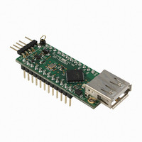
MOD MCU-USB HOST CTLR 24-DIP
Manufacturer
FTDI, Future Technology Devices International Ltd
Series
Vinculum-IIr
Datasheet
1.V2DIP1-32.pdf
(21 pages)
Specifications of V2DIP1-32
Main Purpose
Interface, USB 2.0 Host/Controller
Embedded
Yes, ASIC
Utilized Ic / Part
VNC2-32Q
Primary Attributes
Single A-Type Connector, UART / Parallel FIFO / SPI Interfaces
Secondary Attributes
Second USB Port is Available via Pins, Traffic LEDs
Lead Free Status / RoHS Status
Lead free / RoHS Compliant
Other names
768-1058


3.2 Pin Signal Description
Table 3.1 - Pin Signal Descriptions
Pin No.
J1-10
J1-11
J1-12
J2-10
J2-11
J2-12
J1-1
J1-2
J1-3
J1-4
J1-5
J1-6
J2-7
J1-9
J2-1
J2-2
J2-3
J1-4
J1-5
J2-6
J1-7
J2-8
J2-9
J1-8
IOBUS11
IOBUS10
USBD1M
Name
USBD1P
RESET#
IOBUS4
IOBUS5
IOBUS6
IOBUS7
IOBUS8
IOBUS9
IOBUS3
IOBUS2
IOBUS1
IOBUS0
PROG#
GND
GND
5V0
3V3
-
-
-
-
Pin Name on
Copyright © 2010 Future Technology Devices International Limited
`
PCB
PRG#
RST#
IO11
IO10
U1M
GND
GND
5V0
U1P
3V3
IO4
IO5
IO6
IO7
IO8
IO9
IO3
IO2
IO1
IO0
-
-
-
-
3.3V Output from
VDIP2’s on board
V2DIP1-32 VNC2-32Q Development Module Datasheet Version 1.01
3.3V L.D.O.
PWR Input
Type
Input
Input
PWR
PWR
I/O
I/O
I/O
I/O
I/O
I/O
I/O
I/O
I/O
I/O
I/O
I/O
I/O
I/O
-
-
-
-
USB host / slave port 1 - USBData Signal Minus with
integrated pull up / pull down resistor. Module has on
board 27 Ω USB series resistor. This pin can be
brought out along with pin 5 to provide a second USB
port,if required.
This pin is used in combination with the RESET# pin
and the UART interface to program firmware into the
VNC2.
5.0V module supply pin. This pin can be used to
provide the 5.0V input to the V2DIP1-32 when the
V2DIP1-32 is not powered from the USB connector
(VBUS) or the debugger interface. Also connected to
DIL connector pins pin J3-6.
Not connected
Not connected
USB host / slave port 1 - USBData Signal Plus with
integrated pull up / pull down resistor. Module has on
board 27 Ω USB series resistor. This pin can be
brought out along with pin J1-5 to provide a second
USBport, if required.
5V safe bidirectional data / control bus bit 4
Module ground supply pin
5V safe bidirectional data / control bus bit 5
5V safe bidirectional data / control bus bit 6
5V safe bidirectional data / control bus bit 7
5V safe bidirectional data / control bus bit 8
5V safe bidirectional data / control bus bit 9
3.3V output from V2DIP1’s on board 3.3V L.D.O.
Can be used by an external device to reset the VNC2.
This pin is also used in combination with PROG# and
the UART interface to program firmware into the
VNC2
Not connected
Not connected
5V safe bidirectional data / control bus bit 3
Module ground supply pin
5V safe bidirectional data / control bus bit 2
5V safe bidirectional data / control bus bit 1
5V safe bidirectional data / control bus bit 0
5V safe bidirectional data / control bus bit 11
5V safe bidirectional data / control bus bit 10
Document Reference No.: FT_000163
Description
Clearance No.: FTDI# 150
6
Related parts for V2DIP1-32
Image
Part Number
Description
Manufacturer
Datasheet
Request
R

Part Number:
Description:
MOD MCU-USB HOST CTLR 24-DIP
Manufacturer:
FTDI, Future Technology Devices International Ltd
Datasheet:

Part Number:
Description:
MOD MCU-USB HOST CTLR 60-DIP
Manufacturer:
FTDI, Future Technology Devices International Ltd
Datasheet:

Part Number:
Description:
IC USB TO SERIAL UART 32-QFN
Manufacturer:
FTDI, Future Technology Devices International Ltd

Part Number:
Description:
IC USB HOST CTLR VINCULUM 48LQFP
Manufacturer:
FTDI, Future Technology Devices International Ltd
Datasheet:

Part Number:
Description:
IC USB HOST VINCULUM-II 32QFN
Manufacturer:
FTDI, Future Technology Devices International Ltd
Datasheet:
Part Number:
Description:
IC USB HOST VINCULUM-II 32LQFN
Manufacturer:
FTDI, Future Technology Devices International Ltd
Datasheet:
Part Number:
Description:
IC USB HOST VINCULUM-II 48QFN
Manufacturer:
FTDI, Future Technology Devices International Ltd
Datasheet:
Part Number:
Description:
IC USB HOST VINCULUM-II 32LQFN
Manufacturer:
FTDI, Future Technology Devices International Ltd
Datasheet:
Part Number:
Description:
IC USB HOST VINCULUM-II 32QFN
Manufacturer:
FTDI, Future Technology Devices International Ltd
Datasheet:
Part Number:
Description:
IC USB HOST VINCULUM-II 48LQFP
Manufacturer:
FTDI, Future Technology Devices International Ltd
Datasheet:
Part Number:
Description:
IC USB HOST VINCULUM-II 48LQFP
Manufacturer:
FTDI, Future Technology Devices International Ltd
Datasheet:
Part Number:
Description:
IC USB HOST VINCULUM-II 48QFN
Manufacturer:
FTDI, Future Technology Devices International Ltd
Datasheet:
Part Number:
Description:
IC USB HOST CTLR VINCULUM 64QFN
Manufacturer:
FTDI, Future Technology Devices International Ltd
Datasheet:

Part Number:
Description:
IC USB HOST CTLR VINCULUM 64LQFP
Manufacturer:
FTDI, Future Technology Devices International Ltd
Datasheet:
Part Number:
Description:
IC USB HOST VINCULUM-II 64LQFP
Manufacturer:
FTDI, Future Technology Devices International Ltd
Datasheet: