MCP3909RD-1PH1 Microchip Technology, MCP3909RD-1PH1 Datasheet - Page 13
MCP3909RD-1PH1
Manufacturer Part Number
MCP3909RD-1PH1
Description
BOARD DES MCP3909 ENERGY METER
Manufacturer
Microchip Technology
Datasheets
1.MCP3909T-ISS.pdf
(44 pages)
2.MCP3909RD-1PH1.pdf
(60 pages)
3.MCP3909RD-1PH1.pdf
(6 pages)
Specifications of MCP3909RD-1PH1
Main Purpose
Power Management, Energy/Power Meter
Embedded
Yes, MCU, 8-Bit
Utilized Ic / Part
MCP3909, PIC18F85J90
Primary Attributes
Single Phase Shunt Energy Meter
Secondary Attributes
16 Bit ADC
Ic Function
Single Phase Energy Measurement IC
Supply Voltage Range
4.5V To 5.5V
Operating Temperature Range
-40°C To +85°C
Digital Ic Case Style
SSOP
No. Of Pins
24
Interface Type
SPI
Lead Free Status / RoHS Status
Contains lead / RoHS non-compliant
Lead Free Status / RoHS Status
Contains lead / RoHS non-compliant


2.1
FIGURE 2-1:
© 2009 Microchip Technology Inc.
Note:
LINE_SHUNT2
LINE_SHUNT1
INPUT AND ANALOG FRONT END
(external to
PCB part of
meter case)
NEUTRAL
Shunt
FB = ferrite beads. Ferrite beads have an impedance of the
specified value at 100 MHz.
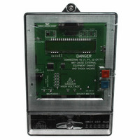
This meter comes populated with components designed for 220V line voltage. At the
bottom of the main board are the high voltage line and neutral connections. There are
four total connections that are made from the PCB to the meter casing, labeled as
LINE, NEUTRAL, SHUNT1 and SHUNT2. The shunt sits on the high or line side of a
two wire system and the meter employes a hot or “live” ground. The wires going into
the shunt to SHUNT1 and SHUNT2 should be twisted together. The wires going into
the LINE and NEUTRAL side of the meter should also be twisted together and kept
away from the SHUNT1 and SHUNT2 wires if possible.
The neutral side of the 2-wire system goes into a resistor divider on the voltage channel
input. Anti-aliasing low-pass filters will be included on both differential channels. The
voltage channel uses two 332 kΩ resistors to achieve a divider ratio of 664:1. For a line
voltage of 230 V
channel of each phase uses current transformer with a turns ratio of 2000:1 and burden
resistance of 56.4 kΩ. The resulting channel 0 signal size is 340 mV
twice the rated maximum current of the meter, still within the input range of the A/D
converter of the MCP3909.
Analog Front End, Phase A Connections and Reference Designators shown.
150 FB (Note)
150 FB (Note)
332 kΩ 332 kΩ
Chapter 2. Hardware
RMS
MCP3909/PIC18F85J90 SINGLE PHASE
ENERGY METER REFERENCE DESIGN
, the channel 1 input signal size will be 490 mV
10 step optional
resistor
ladder
1.0 kΩ
1.0 kΩ
1.0 kΩ
1.0 kΩ
0Ω
68 nF
68 nF
68 nF
68 nF
CH0-
CH0+
CH1+
PEAK
CH1+
MCP3909
PEAK
DS51884A-page 13
. The current
for 20A, or
Related parts for MCP3909RD-1PH1
Image
Part Number
Description
Manufacturer
Datasheet
Request
R

Part Number:
Description:
REF DESIGN FOR MCP3909 W/18F2520
Manufacturer:
Microchip Technology
Datasheet:

Part Number:
Description:
REF DESIGN MCP3909 3PH ENGY MTR
Manufacturer:
Microchip Technology
Datasheet:

Part Number:
Description:
Manufacturer:
Microchip Technology Inc.
Datasheet:
Part Number:
Description:
Manufacturer:
Microchip Technology Inc.
Datasheet:
Part Number:
Description:
Manufacturer:
Microchip Technology Inc.
Datasheet:
Part Number:
Description:
Manufacturer:
Microchip Technology Inc.
Datasheet:
Part Number:
Description:
Manufacturer:
Microchip Technology Inc.
Datasheet:
Part Number:
Description:
Manufacturer:
Microchip Technology Inc.
Datasheet:
Part Number:
Description:
Manufacturer:
Microchip Technology Inc.
Datasheet:
Part Number:
Description:
Manufacturer:
Microchip Technology Inc.
Datasheet: