MCP2515DM-BM Microchip Technology, MCP2515DM-BM Datasheet - Page 13
MCP2515DM-BM
Manufacturer Part Number
MCP2515DM-BM
Description
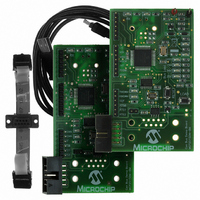
BOARD DEMO FOR MCP2515/51
Manufacturer
Microchip Technology
Series
PICtail™r
Specifications of MCP2515DM-BM
Main Purpose
Interface, CAN Controller
Embedded
Yes, MCU, 8-Bit
Utilized Ic / Part
MCP2515, MCP2551
Primary Attributes
Stand alone CAN Controller with SPI
Silicon Manufacturer
Microchip
Silicon Core Number
MCP2515, MCP2551
Features
Two Identical Boards And A CAN Cable For Creating A Small CAN Bus, CAN Bus PC Software
Lead Free Status / RoHS Status
Lead free / RoHS Compliant
Secondary Attributes
-
Lead Free Status / RoHS Status
Lead free / RoHS Compliant
Available stocks
Company
Part Number
Manufacturer
Quantity
Price
Company:

Part Number:
MCP2515DM-BM
Manufacturer:
Microchip Technology
Quantity:
135


2.4
© 2005 Microchip Technology Inc.
FIRMWARE DESCRIPTION
See Figure 2-2 and Figure 2-3 for a simple firmware flow diagram for Node A (Node B
does not contain any firmware).
1. The firmware first configures the PIC16F676 and the MCP2515.
2. The firmware then checks a global flag bit to determine if a message needs to be
3. The firmware checks a global receive flag bit to determine if a message has been
4. The firmware loops back to #2.
FIGURE 2-2:
sent (a message containing the input button value is transmitted once every
224 ms).
2a. Node A sends a message to Node B requesting I/O status (i.e., push button
status).
received by the MCP2515. If yes, the data is read and the LED is set accordingly.
FIRMWARE FLOW DIAGRAM
ServiceIO
InitMCU
Init2515
Start
Installation and Operation
MAIN
DS51572A-page 9
Related parts for MCP2515DM-BM
Image
Part Number
Description
Manufacturer
Datasheet
Request
R

Part Number:
Description:
IC CAN CONTROLLER W/SPI 18SOIC
Manufacturer:
Microchip Technology
Datasheet:

Part Number:
Description:
IC CAN CONTROLLER W/SPI 18DIP
Manufacturer:
Microchip Technology
Datasheet:
Part Number:
Description:
IC CAN CONTROLLER W/SPI 18SOIC
Manufacturer:
Microchip Technology
Datasheet:

Part Number:
Description:
IC CAN CONTROLLER W/SPI 20TSSOP
Manufacturer:
Microchip Technology
Datasheet:
Part Number:
Description:
IC CAN CONTROLLER W/SPI 20TSSOP
Manufacturer:
Microchip Technology
Datasheet:

Part Number:
Description:
IC,LAN TRANSCEIVER,SINGLE,CMOS,DIP,18PIN,PLASTIC
Manufacturer:
Microchip Technology
Datasheet:
Part Number:
Description:
CAN controller with SPI interface, 125 deg C, -40C to +125C, 18-PDIP, TUBE
Manufacturer:
Microchip Technology
Datasheet:

Part Number:
Description:
Manufacturer:
Microchip Technology Inc.
Datasheet:
Part Number:
Description:
Manufacturer:
Microchip Technology Inc.
Datasheet:
Part Number:
Description:
Manufacturer:
Microchip Technology Inc.
Datasheet:
Part Number:
Description:
Manufacturer:
Microchip Technology Inc.
Datasheet:
Part Number:
Description:
Manufacturer:
Microchip Technology Inc.
Datasheet: