MCP3905RD-PM1 Microchip Technology, MCP3905RD-PM1 Datasheet - Page 14
MCP3905RD-PM1
Manufacturer Part Number
MCP3905RD-PM1
Description
REFERENCE DESIGN FOR MCP3905
Manufacturer
Microchip Technology
Specifications of MCP3905RD-PM1
Main Purpose
Power Management, Energy/Power Meter
Embedded
No
Utilized Ic / Part
MCP3905/6
Primary Attributes
1-Phase, 220 VAC, In Case, With Mechanical Counter
Secondary Attributes
On Board Transformerless AC/DC 5V Supply
Silicon Manufacturer
Microchip
Silicon Core Number
MCP3905A,MCP3906A
Kit Application Type
Power Management
Application Sub Type
Energy Meter
Kit Contents
Design Guides
Lead Free Status / RoHS Status
Lead free / RoHS Compliant
Available stocks
Company
Part Number
Manufacturer
Quantity
Price
Company:

Part Number:
MCP3905RD-PM1
Manufacturer:
MICROCHIP
Quantity:
12 000


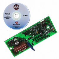
MCP3905A/06A Energy Meter Reference Design
FIGURE 2-3:
2.5
DS51565B-page 10
FRONT-SIDE OF PCB DETAILED DESCRIPTION
MCP3905A/06A Energy Meter Reference Design Block Diagram.
2.5.1
Positions for both logic-high and logic-low are here for all gain and frequency constant
selections. The logic-high positions are labeled “J1H” and the logic-low positions are
labeled “J1L” (Jumper 1 used here as an example). Do not short both the high and the
low positions for any one jumper.
2.5.2
Calibration resistors for each of these jumper locations are located directly beneath the
associated jumper. When a shorting resistor or jumper is in place, the associated
calibration resistor is shorted and bypassed.
2.5.3
JP5 and JP6 are the differential output drive for the mechanical counter.
JP7 is the calibration or microcontroller output that is connected to HF
MCP3905A/06A devices. A LED is supplied to assist in any optical calibration
schemes.
2.5.4
These two connections lead directly through LRC filtering into Channel 0 of the
MCP3905A/06A. The schematic in Appendix A uses a low-cost shunt as the
current-sensing element. The shunt resistance should be placed in parallel with these
two connections, between JP1 and JP2.
Current Conn.
(JP1,JP2)
DC Power
Selection (J11-J15)
Supply
Power Supply
Shunts for Gain,
Ground Plane
FC and HPF
Shunts for Gain and FC Selection (J11-J15)
Calibration Jumpers (J1-J10)
Output Connections for Mechanical Counter and Calibration
(JP5-JP7)
Connection to Current-Sensing Element (JP1,JP2)
Ground Plane
Jumpers (J1-J10)
Analog
Calibration
Opto.
Isolator (U3)
FRONT
BACK
Output Connections (JP5-JP7)
Ground Plane
Analog
MCP3905A
Ground Plane
Power Supply
Voltage Conn.
(JP3,JP4)
© 2009 Microchip Technology Inc.
(U1)
OUT
on the
Related parts for MCP3905RD-PM1
Image
Part Number
Description
Manufacturer
Datasheet
Request
R

Part Number:
Description:
IC ENERGY METER 24-SSOP
Manufacturer:
Microchip Technology
Datasheet:

Part Number:
Description:
Energy-Metering ICs with Active (Real) Power Pulse Output
Manufacturer:
Microchip Technology
Part Number:
Description:
(MCP3905 / MCP3906) Energy-Metering ICs
Manufacturer:
Microchip Technology
Datasheet:

Part Number:
Description:
Manufacturer:
Microchip Technology Inc.
Datasheet:
Part Number:
Description:
Manufacturer:
Microchip Technology Inc.
Datasheet:
Part Number:
Description:
Manufacturer:
Microchip Technology Inc.
Datasheet:
Part Number:
Description:
Manufacturer:
Microchip Technology Inc.
Datasheet:
Part Number:
Description:
Manufacturer:
Microchip Technology Inc.
Datasheet:
Part Number:
Description:
Manufacturer:
Microchip Technology Inc.
Datasheet:
Part Number:
Description:
Manufacturer:
Microchip Technology Inc.
Datasheet: