MCP3905RD-PM1 Microchip Technology, MCP3905RD-PM1 Datasheet - Page 12
MCP3905RD-PM1
Manufacturer Part Number
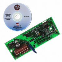
MCP3905RD-PM1
Description
REFERENCE DESIGN FOR MCP3905
Manufacturer
Microchip Technology
Specifications of MCP3905RD-PM1
Main Purpose
Power Management, Energy/Power Meter
Embedded
No
Utilized Ic / Part
MCP3905/6
Primary Attributes
1-Phase, 220 VAC, In Case, With Mechanical Counter
Secondary Attributes
On Board Transformerless AC/DC 5V Supply
Silicon Manufacturer
Microchip
Silicon Core Number
MCP3905A,MCP3906A
Kit Application Type
Power Management
Application Sub Type
Energy Meter
Kit Contents
Design Guides
Lead Free Status / RoHS Status
Lead free / RoHS Compliant
Available stocks
Company
Part Number
Manufacturer
Quantity
Price
Company:

Part Number:
MCP3905RD-PM1
Manufacturer:
MICROCHIP
Quantity:
12 000


MCP3905A/06A Energy Meter Reference Design
2.3
DS51565B-page 8
GETTING STARTED
This meter can be manufactured by performing the following two steps detailed in this
document. For the external connections, the following terms are used: “phase” refers
to the hot (or line) side of the power supply lines. “Neutral” refers to the return wire
(or low-side) of the power supply lines.
2.3.1
Connections are made to the phase and neutral wire for voltage-detection and AC/DC
power supply. The MCP3905A/06A Energy Meter Reference Design is designed to be
biased to the phase (or hot) side of a 2-wire power supply system.
1. Connect JP4 to the phase power supply line connection.
2. Connect JP3 to the neutral line.
3. Connect JP1 and JP2 across the shunt.
4. Connect JP5 and JP6 to the mechanical counter.
2.3.2
Each meter must be calibrated using the voltage divider circuit going into Channel 1 of
the MCP3905A/06A. A known power is supplied to the meter (e.g., 1000W), and an
expected output frequency is the goal (1000 imp/kWh). Start with the highest value
resistor and short the resistor using it's respective shorting jumper. If the output
frequency is too high, remove the shunt. Continue testing each resistor short until all
jumpers are tested once. For more detailed information regarding meter calibration and
the PCB design approach using the circuitry in this document, refer to AN994,
“IEC Compliant Active Energy Meter Design Using The MCP3905A/06A” (DS00994).
FIGURE 2-2:
External Connections
Calibration of the Frequency Output using the Voltage Divider
Calibration Circuit
Photograph of Complete, Stand-Alone MCP3905A Energy Meter.
© 2009 Microchip Technology Inc.
Related parts for MCP3905RD-PM1
Image
Part Number
Description
Manufacturer
Datasheet
Request
R

Part Number:
Description:
IC ENERGY METER 24-SSOP
Manufacturer:
Microchip Technology
Datasheet:

Part Number:
Description:
Energy-Metering ICs with Active (Real) Power Pulse Output
Manufacturer:
Microchip Technology
Part Number:
Description:
(MCP3905 / MCP3906) Energy-Metering ICs
Manufacturer:
Microchip Technology
Datasheet:

Part Number:
Description:
Manufacturer:
Microchip Technology Inc.
Datasheet:
Part Number:
Description:
Manufacturer:
Microchip Technology Inc.
Datasheet:
Part Number:
Description:
Manufacturer:
Microchip Technology Inc.
Datasheet:
Part Number:
Description:
Manufacturer:
Microchip Technology Inc.
Datasheet:
Part Number:
Description:
Manufacturer:
Microchip Technology Inc.
Datasheet:
Part Number:
Description:
Manufacturer:
Microchip Technology Inc.
Datasheet:
Part Number:
Description:
Manufacturer:
Microchip Technology Inc.
Datasheet: