EVB-USB2524 SMSC, EVB-USB2524 Datasheet - Page 45
EVB-USB2524
Manufacturer Part Number
EVB-USB2524
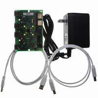
Description
BOARD EVAL USB2524 SHARE/SWITCH
Manufacturer
SMSC
Series
MultiSwitch™r
Specifications of EVB-USB2524
Main Purpose
Interface, USB 2.0 Hub
Embedded
No
Utilized Ic / Part
USB2524
Primary Attributes
Quad Port Hub, High Speed (480Mbps), SMBus
Secondary Attributes
Overcurrent Protection, Port Power Switching, Multi-TT Enabled
Interface Type
USB
Operating Supply Voltage
5 V
Product
Interface Modules
Lead Free Status / RoHS Status
Lead free / RoHS Compliant
For Use With/related Products
USB2524
Other names
638-1044
Available stocks
Company
Part Number
Manufacturer
Quantity
Price
Company:

Part Number:
EVB-USB2524
Manufacturer:
SMSC
Quantity:
135


USB MultiSwitch
Datasheet
SMSC USB2524
8.3
All 8 LED pins are used in this mode in conjunction with 8 Dual-color LEDs (each LED pair in a single
package) to indicate which upstream Host owns each specific downstream Port, as well as the speed
that the downstream device is operating at.
Each dual-color LED provides two separate colors (commonly Green and Red). If each of these
separate colors are pulsed on and off at a rapid rate, a user will see a third color (in this example,
Orange). By this means, 4 different “color” states are possible (Green, Red, Orange, and Off).
Figure 8.1
to be replicated for each of the 8 LED pins on the USB2524. In this circuit, when the LED pin is driven
to a logic low state, the Green LED will Light up. When the LED pin is driven to a Logic High state
the Red LED will Light up. When a 1KHz square wave is driven out on the LED pin, the Green and
Red LED’s will both alternately light up giving the effect of the color Orange. When nothing is driven
out on the LED pin (i.e. the pin floats to a “tri-state” condition), neither the Green or Red LED will light
up, this is the “Off” state.
Host Ownership and Port Speed LED Indication:
TM
Hub
LED pin
shows a simple example of how this LED circuit will be implemented. The Circuit will need
3.3V
Figure 8.1 Dual Color LED Implementation Example
Current limiting
resistor
General
Purpose
Diode
DATASHEET
45
Green LED
Red LED
Connect to other
dual color diodes.
Revision 1.91 (08-22-07)
Related parts for EVB-USB2524
Image
Part Number
Description
Manufacturer
Datasheet
Request
R

Part Number:
Description:
BOARD EVAL FOR USB2514 48-QFN
Manufacturer:
SMSC
Datasheet:

Part Number:
Description:
Networking Modules & Development Tools LAN7500 USB 2.0 BRD 10/100/1000 GigB
Manufacturer:
SMSC
Datasheet:

Part Number:
Description:
BOARD EVAL FOR USB2514/USB2514I
Manufacturer:
SMSC
Datasheet:

Part Number:
Description:
BOARD EVAL FOR USB2512/USB2512I
Manufacturer:
SMSC
Datasheet:

Part Number:
Description:
BOARD EVAL FOR USB2513/USB2513I
Manufacturer:
SMSC
Datasheet:

Part Number:
Description:
BOARD EVALUATION FOR EMC1043
Manufacturer:
SMSC
Datasheet:
Part Number:
Description:
EVALUATION BOARD FOR USB3311C
Manufacturer:
SMSC
Datasheet:
Part Number:
Description:
EVALUATION BOARD FOR USB3317C
Manufacturer:
SMSC
Datasheet:

Part Number:
Description:
EVALUATION BOARD USB2241-AEZG
Manufacturer:
SMSC
Datasheet:

Part Number:
Description:
BOARD EVALUATION FOR USB2502
Manufacturer:
SMSC
Datasheet:
Part Number:
Description:
BOARD EVALUATION FOR USB2504
Manufacturer:
SMSC
Datasheet:

Part Number:
Description:
EVALUATION BOARD LAN9500-ABZJ
Manufacturer:
SMSC
Datasheet:
Part Number:
Description:
Ethernet Modules & Development Tools LAN9500 Design Kit Low-Cost USB Dongle
Manufacturer:
SMSC
Datasheet:
Part Number:
Description:
Interface Modules & Development Tools Eval BRD-USB2602
Manufacturer:
SMSC
Datasheet: